10
16
14
12
10
8
6
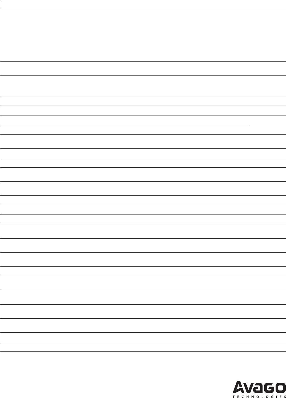
THRESHOLD-TO-NOISE RATIO - (Vp-p/VRMS)
1E-151E-3 1E-5 1E-7 1E-9 1E-11 1E-13
BIT-ERROR RATIO - (BER)
Figure 8. Receiver Threshold-to-Noise Ratio vs. Probability of Error
(aka BER)
Error Rates and Noise Immunity
The probability that a fiberoptic link will make an error
is related to the receivers own internal random noise
and its ability to reject noise originating from the sys-
tem in which it is installed. The total noise present in
any fiberoptic receiver is normally the sum of the PIN
diode preamplifier’s noise and the host system’s elec-
trical noise. The amount of hysteresis applied to the
comparator determines the minimum signal amplitude
(also known as minimum signal threshold level) at
which the receiver can reliably detect data. The ratio
between the comparators switching threshold (also
known as hysteresis) and the receiver’s noise also has a
dramatic impact on probability of error. Small increases
in the comparator’s threshold-to-noise ratio result in a
very sharp reduction in the probability of error. Figure 8
shows that the receiver’s probability of error is reduced
by six orders of magnitude from (1x10⁻⁹ to 1x10-15)
when the receivers threshold-tonoise ratio improves
from 12:1 to 15.8:1. At any fixed temperature the total
value of the receiver’s random noise plus the host sys-
tems noise can be assumed to be a constant. So the
most obvious way to reduce the probability of error is
to increase the comparator’s hysteresis and increase the
amplitude of the optical signal applied to the receiver. A
less obvious but better technique for lowering the error
rate is to improve the receivers ability to reject electrical
noise from the system in which it resides. The fiberoptic
receivers recommended in this application note have
sufficient noise immunity to be used in most systems
without electrostatic shielding. The Avago Technologies
PIN diode pre-amps, which are used in the receivers
first stage, are small hybrid circuits, and these small
hybrid components do not function as particularly
effective antennas. For extremely noisy applications,
Avago Technologies offers PIN diode pre-amps in elec-
trically conductive plastic or all metal packages. Avago
Technologies manufactures a wide range of conductive
and non-conductive fiberoptic components that mate
with various industry-standard fiberoptic connectors.
However, the overwhelming majority of the fiberoptic
applications successfully implemented with Avago
Technologies’ fiberoptic components have not required
conductive plastic or metal receiver housings. The most
insidious and the most overlooked source of noise is
usually the host systems +5 V power supply. The host
systems +5 volt supply normally powers the fiberoptic
receiver, the fiberoptic transmitter and an entire system
comprised of relatively noisy digital circuits. The simple
and inexpensive power supply filters recommended
in this publication have been proven to work in a wide
range of system applications. The power-supply filters
recommended in this application note are normally suf-
ficient to protect the fiberoptic receiver from very noisy
host systems, but in extremely noisy applications addi-
tional power supply filtering could be needed.
Parts List
The TTL-compatible fiberoptic transceivers recommend-
ed in this publication are very simple and inexpensive,
so only a few external components are needed. Com-
plete parts lists for the circuits recommended in this ap-
plication note are provided in Table 5 and Table 6. The
parts listed in Table 5 are for the transmitter in Figure
3 and the receiver in Figure 4. The parts listed in Table
6 are for the transmitter in Figure 3 and the receiver in
Figure 5. All of the components described in the part
lists are compatible with the printed circuit artworks
shown in Figure 6 and Figure 7, thus minimizing the
design time and resources needed to use the low cost
fiberoptic transceivers shown in the application note.
11
Table 5. Parts List for the Transmitter in Figure 3 and Receiver in Figure 4
Conclusion
The complete TTL-compatible fiberoptic transceiver
solutions provided in this publication can be used to
improve the noise immunity of existing data communi-
cation systems that use protocols originally developed
for use with copper wire. When fiberoptic media is used
in place of conventional copper wire, it is possible to
build new communication systems that are immune to
large noise transients caused by utility power switch
gear, motor drives or high voltage power supplies.
Furthermore the non-conductive cables used in optical
communication links have an intrinsically higher prob-
ability of surviving lightning strikes than copper wire
alternatives. The optical data communication solutions
shown in this application note are also capable of send-
ing highspeed 32 MBd data over long distances that
would be impractical with copper wire cables. System
designers can quickly develop noise-immune com-
munication links with minimal engineering costs by
embedding the complete fiberoptic solution shown in
this application note.
Designator Part Type Description Footprint Material Part Number Quantity Vendor 1
C1
C5
C8
C9
C11
C13
0.1 mF
0.1 mF
0.1 mF
0.1 mF
0.1 mF
0.1 mF
Capacitor
Capacitor
Capacitor
Capacitor
Capacitor
Capacitor
805 X75 or
better
C0805X7R500104KNE 6 Venkel
C6
C7
Determined
by Equation 1
Capacitor
Capacitor
805
805
NPO/COG
NPO/COG
1
1
Venkel
C2
C10
C12
10 mF
10 mF
10 mF
Capacitor
Capacitor
Capacitor
B Tantalum,
10V
TA010TCM106MBN 3 Venkel
C3 See Table 2 Capacitor 805 NPO/COG 1 Venkel
U1 I.C. Nand Gate S014 74ACTQ00 1 Fairchild
U2 Fiberoptic Transmitter See Table 2 HFBR-1XXXZ 1 Avago
Technologies
U3 Fiberoptic Receiver See Table 4 HFBR-2XXXZ 1 Avago
Technologies
U4 LT1016 IC, comparator S08 LT1016CS8 1 Linear Tech
L1 CB70-1812 Inductor 1812 HF30ACB453215 1 TDK
L2
L3
1.2 mH
Inductor 10% 1008LS-122XKBC 2 Coilcraft
R4
R5
4.7 W
4.7 W
Resistor
Resistor
805 5% CR080510W4R7JT 2 Venkel
R1 See Table 2 Resistor 805 1% 1 Venkel
R2 See Table 2 Resistor 805 1% 1 Venkel
R3 See Table 2 Resistor 805 1% 1 Venkel
R6
R7
270 W
270 W
Resistor 805 5% CR080510W271JT 2 Venkel
R8
R9
120 kW
120 kW
Resistor 805 5% CR080510W241JT 2 Venkel
R10
R11
240 W
240 W
Resistor 805 5% CR080510W241JT 2 Venkel
R12
2.2 kW
Resistor 805 5% CR080510W222JT 1 Venkel
J1 Pins 343B 9 McKenzie
Table 6. Parts List for the Transmitter in Figure 3 and Receiver in Figure 5
Designator Part Type Description Footprint Material Part Number Quantity Vendor 1
C1
C6
C7
C8
C11
C12
C14
C16
0.1 mF
0.1 mF
0.1 mF
0.1 mF
0.1 mF
0.1 mF
0.1 mF
0.1 mF
Capacitor
Capacitor
Capacitor
Capacitor
Capacitor
Capacitor
Capacitor
Capacitor
805 X7R or
Better
C0805X7R500104KNE 8 Venkel
C9
C10
Determined by
Equation 2
Capacitor
Capacitor
805
805
NPO/COG
NPO/COG
1
1
Venkel
Venkel
C2
C13
C15
10 mF
10 mF
10 mF
Capacitor
Capacitor
Capacitor
B Tantalum,
10 V
TA010TCM106MBN 3 Venkel
C3 See Table 2 Capacitor 805 NPO/COG 1 Venkel
U1 I.C. Nand Gate S014 74ACTQ00 1 Fairchild
U2 Fiberoptic Transitter See Table 2 HFBR-1XXXZ 1 Avago
Technologies
U3 Fiberoptic Receiver See Table 4 HFBR-2XXXZ 1
U4 LT1016 IC,
comparator
S08 LT1016CS8 1 Linear Tech
U5 Quad NPN Transistor S016 MMPQ3904 1 Motorola
L1 CB70-1812 Inductor 1812 HF30ACB453215 1 TDK
L2
L3
1.2 mH
Inductor 10% 108LS-122XKBC 2 Coilcraft
R4
R5
4.7 W
4.7 W
Resistor
Resistor
805 5% CR080510W4R7JT 2 Venkel
R1 See Table 2 Resistor 805 1% 1 Venkel
R2 See Table 2 Resistor 805 1% 1 Venkel
R3 See Table 2 Resistor 805 1% 1 Venkel
R6
R11
2.4 kW
2.4 kW
Resistor 805 5% CR080510W242JT 2 Venkel
R7
R12
1.5 kW
1.5 kW
Resistor 805 5% CR080510W152JT 2 Venkel
R8
R9
51 W
51 W
Resistor 805 5% CR080510W510JT 2 Venkel
R10
110 W
Resistor 805 5% CR080510W111JT 1 Venkel
R13
R14
470 W
470 W
Resistor 805 5% CR080510W471JT 2 Venkel
R15
R16
270 W
270 W
Resistor 805 5% CR080510W271JT 2 Venkel
R17
R18
68 kW
68 kW
Resistor 805 5% CR080510W163JT 2 Venkel
R19
R20
240 W
240 W
Resistor 805 5% CR080510W241JT 2 Venkel
R21
2.2 kW
Resistor 805 5% CR080510W222JT 1 Venkel
J1 Pins 343B 9 McKenzie
For product information and a complete list of distributors, please go to our web site: www.avagotech.com
Avago, Avago Technologies, and the A logo are trademarks of Avago Technologies in the United States and other countries.
Data subject to change. Copyright © 2005-2010 Avago Technologies. All rights reserved.
AV02-0723EN - July 22, 2010

HFBR-0537

Mfr. #:
Manufacturer:
Broadcom / Avago
Description:
Fiber Optic Development Tools 32MBd Data Comm Evaluation Kit
Lifecycle:
New from this manufacturer.
Delivery:
DHL FedEx Ups TNT EMS
Payment:
T/T Paypal Visa MoneyGram Western Union

Products related to this Datasheet