SQCB7M2R4BATME

8
192
062116
RF/Microwave MLC’s
SQ Series Ultra Low ESR MLC
SQ
AVX Style
CA
Case Size
CA = 0505
CB = 1111
See mechanical
dimensions below
7
Voltage
Code
5 = 50V
1 = 100V
E = 150V
2 = 200V
V = 250V
9 = 300V
7 = 500V
C = 600V
A = 1000V
S = 1500V
M 100 J A
Failure Rate
Code
A = Not
Applicable
T1A
FEATURES:
• Low ESR
• High Q
• High Self Resonance
• Capacitance Range 0.1 pF to 5100 pF
• 175ºC Capability SQCB
(Standard voltages only)
APPLICATIONS:
• RF Power Amplifiers
• Low Noise Amplifiers
• Filter Networks
• MRI Systems
HOW TO ORDER
Temperature
Coefficient Code
M = +90±20ppm/°C
A = 0±30ppm/°C
C = 15% (“J” Termination only)
Termination Style Code
**T = 100% Tin
J = Nickel Barrier Sn/Pb
(60/40)
**7 = Ag/Ni/Au
H = Cu/Sn (Non-Magnetic)
Capacitance
Tolerance Code
B = ±.1 pF
C = ±.25 pF
D = ±.5 pF
F = ±1%
G = ±2%
J = ±5%
K = ±10%
M = ±20%
N = ±30%
Capacitance
EIA Capacitance Code in pF.
First two digits = significant
figures or “R” for decimal
place.
Third digit = number of zeros
or after “R” significant figures.
TAPE & REEL: All tape and reel specifications are in compliance with EIA RS481 (equivalent to IEC 286 part 3).
—8mm carrier
—7" reel: SQCA/SQCB = 1000 pcs
WAFFLE PACK
SQCA 100 pcs
SQCB 100 pcs
Packaging Code
1A = 7" Reel Unmarked
6A = Waffle Pack Unmarked
ME = 7" Reel Marked
WE = Waffle Pack Marked
* Vertical T&R available
Case Length (L) Width (W) Thickness (T) Band Width (bw)
SQCA*
.055 + .015 - .010 .055±.015 .020/.057 .010 + .010 -.005
(1.40+ .381 - .254) (1.40±.381) (.508/1.45) (.254 +.254 -.127)
SQCB*
.110 + .020 - .010 .110±.010 .030/.102 .015±.010
(2.79 +.508 -.254) (2.79±.254) (.762/2.59) (.381±.254)
MECHANICAL DIMENSIONS: inches (millimeters)
L
W
T
bw
**RoHS compliant
Not RoHS Compliant
LEAD-FREE COMPATIBLE
COMPONENT
For RoHS compliant products,
please select correct termination style.
8
193
062116
RF/Microwave MLC’s
SQ Series Ultra Low ESR MLC
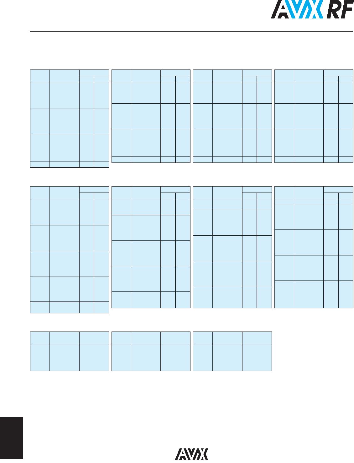
ELECTRICAL SPECIFICATIONS
Dielectric M & A C
Temperature Coefficient (TCC) (M) +90 ± 20 PPM/ºC ( -55ºC to +125ºC) ±15% (-55ºC to 125ºC)
(M) +90 ± 30 PPM/ºC ( +125ºC to +175ºC)*
(A) 0 ± 30 PPM/ºC
Capacitance Range (M) 0.1 pF to 1000 pF 0.001μF to 0.1μF
(A) 0.1 pF to 5100 pF
Operating Temperature A Case: -55ºC to +125ºC* -55°C to +125°C
B Case (M Dielectric):
0.1 pF to 330 pF: from -55ºC to +175ºC
360 pF to 5100 pF: from -55ºC to +125ºC
B Case (A Dielectric):
0.1 pF to 200 pF: from -55ºC to +175ºC
220 pF to 5100 pF: from -55ºC to +125ºC
Quality Factor (Q) M Dielectric A & B Case Greater than 10,000 at 1 MHz 2.5% @ 1kHz
A Dielectric B Case Greater than 10,000 at 1 MHz 0.1 - 200 pF
Greater than 2,000 at 1 MHz 220 - 1000 pF
Greater than 2,000 at 1 KHz 1100 - 5100 pF
A Dielectric A Case Greater than 10,000 at 1 MHz 0.1 - 100 pF
Greater than 2,000 at 1 MHz 110 - 1000 pF
Insulation Resistance (IR) 0.2 pF to 470 pF 10
4
Megohms min. @ 25ºC at rated WVDC
10
6
Megohms min. @ 25ºC at rated WVDC 10
3
Megohms min. @ 125ºC at rated WVDC
10
5
Megohms min. @ 125ºC at rated WVDC
510 pF to 5100 pF
10
5
Megohms min. @ 25ºC at rated WVDC
10
4
Megohms min. @ 125ºC at rated WVDC
Working Voltage (WVDC) See Capacitance Values table See Capacitance Values table
Dielectric Withstanding Voltage (DWV) WVDC 500V or less: 250% of rated WVDC for 5 seconds 250% of rated WVDC for 5 secs
WVDC 1250V or less: 150% of rated WVDC for 5 seconds
WVDC > 1250V: 120% of rated WVDC for 5 seconds
Aging Effects None <3% per decade hour
Piezoelectric Effects None None
Capacitance Drift ± (0.02% or 0.02 pF), whichever is greater Not Applicable
Themal Shock Mil-STD-202, Method 107, Condition A
Moisture Resistance Mil-STD-202, Method 106
Low Voltage Humidity Mil-STD-202, Method 103, condition A, with 1.5 VDC
applied while subjected to an environment of 85ºC with
85% relative humidity for 240 hours
Life Test Mil-STD-202, Method 108, for 2000 hours at 125ºC
Shock Mil-STD-202, Method 213, Condition J
Vibration Mil-STD-202, Method 204, Condition B
Immersion Mil-STD-202, Method 104, Condition B
Salt Spray Mil-STD-202, Method 101, Condition B
Solderability Mil-STD-202, Method 208
Terminal Strength Mil-STD-202, Method 211
Temperature Cycling Mil-STD-202, Method 102, Condition C
Barometric Pressure Mil-STD-202, Method 105, Condition B
Resistance to Solder Heat Mil-STD-202, Method 210, Condition C
ENVIRONMENTAL CHARACTERISTICS
AVX SQ will meet and exceed the requirements of EIA-198, MIL-PRF-55681 and MIL-PRF-123
* 175 SQCB only
8
194
062116
RF/Microwave MLC’s
SQ Series Ultra Low ESR MLC
TABLE II: TC: A (0±30PPM/°C)
TABLE III: TC: C (±15%)
Case Size A
TABLE I: TC: M (+90±20PPM/°C)
Cap. pF Cap. Tol.
WVDC*
STD HV
0.1 B 150 250
0.2 B 150 250
0.3 B,C 150 250
0.4 B,C 150 250
0.5 B, C, D 150 250
0.6 B, C, D 150 250
0.7 B, C, D 150 250
0.8 B, C, D 150 250
0.9 B, C, D 150 250
1.0 B, C, D 150 250
1.1 B, C, D 150 250
1.2 B, C, D 150 250
1.3 B, C, D 150 250
1.4 B, C, D 150 250
1.5 B, C, D 150 250
1.6 B, C, D 150 250
Cap. pF Cap. Tol.
WVDC*
STD HV
1.7 B, C, D 150 250
1.8 B, C, D 150 250
1.9 B, C, D 150 250
2.0 B, C, D 150 250
2.2 B, C, D 150 250
2.4 B, C, D 150 250
2.7 B, C, D 150 250
3.0 B, C, D 150 250
3.3 B, C, D 150 250
3.6 B, C, D 150 250
3.9 B, C, D 150 250
4.3 B, C, D 150 250
4.7 B, C, D 150 250
5.1 B, C, D 150 250
5.6 B, C, D 150 250
Cap. pF Cap. Tol.
WVDC*
STD HV
6.2 B, C, D 150 250
6.8 B, C, J, K 150 250
7.5 B, C, J, K 150 250
8.2 B, C, J, K 150 250
9.1 B, C, J, K 150 250
10 F, G, J, K 150 250
11 F, G, J, K 150 250
12 F, G, J, K 150 250
13 F, G, J, K 150 250
15 F, G, J, K 150 250
16 F, G, J, K 150 250
18 F, G, J, K 150 250
20 F, G, J, K 150 250
22 F, G, J, K 150 250
24 F, G, J, K 150 250
Cap. pF Cap. Tol.
WVDC*
STD HV
27 F, G, J, K 150 250
30 F, G, J, K 150 250
33 F, G, J, K 150 250
36 F, G, J, K 150 250
39 F, G, J, K 150 250
43 F, G, J, K 150 250
47 F, G, J, K 150 250
51 F, G, J, K 150 250
56 F, G, J, K 150 250
62 F, G, J, K 150 200
68 F, G, J, K 150 200
75 F, G, J, K 150 200
82 F, G, J, K 150 200
91 F, G, J, K 150 200
100 F, G, J, K 150 200
Cap. pF Cap. Tol.
WVDC*
STD HV
0.1 B 150 250
0.2 B 150 250
0.3 B,C 150 250
0.4 B,C 150 250
0.5 B, C, D 150 250
0.6 B, C, D 150 250
0.7 B, C, D 150 250
0.8 B, C, D 150 250
0.9 B, C, D 150 250
1.0 B, C, D 150 250
1.1 B, C, D 150 250
1.2 B, C, D 150 250
1.3 B, C, D 150 250
1.4 B, C, D 150 250
1.5 B, C, D 150 250
1.6 B, C, D 150 250
1.7 B, C, D 150 250
1.8 B, C, D 150 250
1.9 B, C, D 150 250
2.0 B, C, D 150 250
2.2 B, C, D 150 250
2.4 B, C, D 150 250
Cap. pF Cap. Tol.
WVDC*
STD HV
2.7 B, C, D 150 250
3.0 B, C, D 150 250
3.3 B, C, D 150 250
3.6 B, C, D 150 250
3.9 B, C, D 150 250
4.3 B, C, D 150 250
4.7 B, C, D 150 250
5.1 B, C, D 150 250
5.6 B, C, D 150 250
6.2 B, C, D 150 250
6.8 B, C, J, K 150 250
7.5 B, C, J, K 150 250
8.2 B, C, J, K 150 250
9.1 B, C, J, K 150 250
10 F, G, J, K 150 250
11 F, G, J, K 150 250
12 F, G, J, K 150 250
13 F, G, J, K 150 250
15 F, G, J, K 150 250
16 F, G, J, K 150 250
18 F, G, J, K 150 250
Cap. pF Cap. Tol.
WVDC*
STD HV
20 F, G, J, K 150 250
22 F, G, J, K 150 250
24 F, G, J, K 150 250
27 F, G, J, K 150 250
30 F, G, J, K 150 250
33 F, G, J, K 150 250
36 F, G, J, K 150 250
39 F, G, J, K 150 250
43 F, G, J, K 150 250
47 F, G, J, K 150 250
51 F, G, J, K 150 250
56 F, G, J, K 150 250
62 F, G, J, K 150
200
68 F, G, J, K 150
200
75 F, G, J, K 150
200
82 F, G, J, K 150
200
91 F, G, J, K 150
200
100 F, G, J, K 150
110 F, G, J, K 150
120 F, G, J, K 150
130 F, G, J, K 150
Cap. pF Cap. Tol.
WVDC*
STD HV
150 F, G, J, K 150
160 F, G, J, K 150
180 F, G, J, K 150
200 F, G, J, K 150
220 F, G, J, K 150
240 F, G, J, K 150
270 F, G, J, K 150
300 F, G, J, K 150
330 F, G, J, K 150
360 F, G, J, K 150
390 F, G, J, K 150
430 F, G, J, K 150
470 F, G, J, K 150
510 F, G, J, K 150
560 F, G, J, K 150
620 F, G, J, K 150
680 F, G, J, K 50
750 F, G, J, K 50
820 F, G, J, K 50
910 F, G, J, K 50
1000 F, G, J, K 50
Cap. pF Cap. Tol.
WVDC
STD
1000 K, M, N 50
1200 K, M, N 50
1500 K, M, N 50
1800 K, M, N 50
2000 K, M, N 50
Cap. pF Cap. Tol.
WVDC
STD
2200 K, M, N 50
2700 K, M, N 50
3300 K, M, N 50
3900 K, M, N 50
4700 K, M, N 50
Cap. pF Cap. Tol.
WVDC
STD
5100 K, M, N 50
5600 K, M, N 50
6800 K, M, N 50
8200 K, M, N 50
10000 K, M, N 50
*STD = Standard voltage rating; HV = High voltage rating

SQCB7M2R4BATME

Mfr. #:
Manufacturer:
N/A
Description:
Multilayer Ceramic Capacitors MLCC - SMD/SMT 500volts 2.4pF
Lifecycle:
New from this manufacturer.
Delivery:
DHL FedEx Ups TNT EMS
Payment:
T/T Paypal Visa MoneyGram Western Union