9.53
(.375)
5.64
(.222)
5.97 ± .89
(.235 ± .035)
.38
(.015)
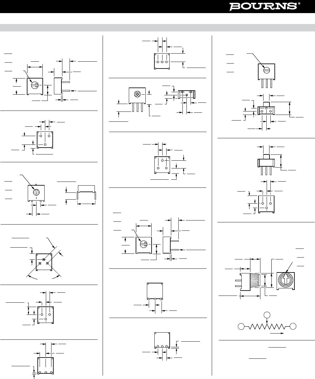
Side Adjust Models H,S,W
3.56 ± .25
(.140 ± .010)
3.81
(.150)
132
4.83
(.190)
3386B
2.54
(.100)
132
3386C
1.40 ± .25
(.055 ± .010)
13
2
3386H
2.44
(.096)
3.81
(.150)
132
3386J
2.44
(.096)
312
3386S
2.44
(.096)
312
3386W
31
2
3386X
ADJ. SLOT
.76
(.030)
.76
(.030)
3.15
(.124)
3.56 ± .25
(.140 ± .010)
1.40 ± .25
(.055 ± .010)
3.81
(.150)
WIDE
X
X
DEEP
LONG
2.54
(.100)
2.54
(.100)
2.54
(.100)
2.54
(.100)
2.54
(.100)
2.54
(.100)
2.54
(.100)
2.54
(.100)
2.54
(.100)
3.81
(.150)
MIN.
9.53
(.375)
5.33
(.210)
.51 ± .05
(.020 ± .002)
5.97 ± .89
(.235 ± .035)
.38
(.015)
Side Adjust Models B,C,J,X
ADJ. SLOT
.76
(.030)
.76
(.030)
3.15
(.124)
WIDE
X
X
DEEP
LONG
9.53
(.375)
9.53
(.375)
MIN.
DIA. PINS
.51 ± .05
(.020 ± .002)
DIA. PINS
3.81
(.150)
3.81
(.150)
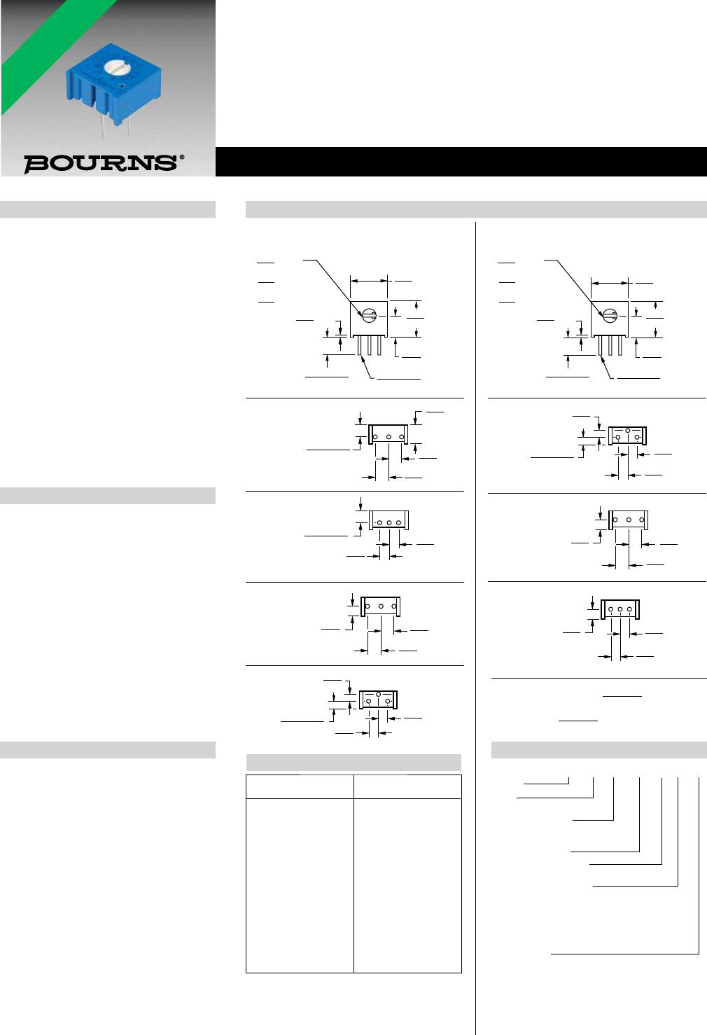
Features
n Single Turn / Cermet / Industrial / Sealed
n Available on tape and reel
n Available with a knob for finger adjust
n Available with extended shaft
n Available with cross-slot rotor
n Top and side adjust types (F, P, H, W, X
most popular)
n RoHS compliant* version available
n For trimmer applications/processing
guidelines, click here
3386 - 3/8 ” Square Trimpot
®
Trimming Potentiometer
*RoHS Directive 2002/95/EC Jan. 27, 2003 including
annex and RoHS Recast 2011/65/EU June 8, 2011.
†“Fluorinert” is a registered trademark of 3M Co.
Specifications are subject to change without notice.
The device characteristics and parameters in this data
sheet can and do vary in different applications and actual device performance may vary over time.
Users should verify actual device performance in their specific applications.
Electrical Characteristics
Standard Resistance Range
......................10 ohms to 2 megohms
(see standard resistance table)
Resistance Tolerance ........... ±10 % std.
(tighter tolerance available)
Absolute Minimum Resistance
....................................... 2 ohms max.
Contact Resistance Variation
........................... 2 % or 3 ohms max.
(whichever is greater)
Adjustability
Voltage Divider ...................... ±0.05 %
Rheostat ................................ ±0.15 %
Resolution ................................... Innite
Insulation Resistance ............... 500 vdc.
1,000 megohms min.
Dielectric Strength
Sea Level................................ 900 vac
70,000 Feet ............................ 350 vac
Adjustment Angle ................. 280 ° nom.
Environmental Characteristics
Power Rating (300 volts max.)
85 °C ......................................0.5 watt
125 °C .......................................0 watt
Temperature Range ... -55 °C to +125 °C
Temperature Coecient ... ±100 ppm/°C
Seal Test ......................85 °C Fluorinert†
Humidity .......MIL-STD-202 Method 103
96 hours
(2 % ΔTR, 10 Megohms min.)
Vibration ....... 30 G (1 % ΔTR; 1 % ΔVR)
Shock ......... 100 G (1 % ΔTR; 1 % ΔVR)
Load Life .. 1,000 hours 0.5 watt @ 70 °C
(3 % ΔTR; 3 % or 3 ohms,
whichever is greater, CRV)
Rotational Life .......................200 cycles
(4 % ΔTR; 3 % or 3 ohms,
whichever is greater, CRV)
Physical Characteristics
Mechanical Angle ................. 310 ° nom.
Torque .............................5.0 oz-in. max.
Stop Strength ...............15.0 oz -in. min.
Terminals .......................Solderable pins
Weight ....................................... 0.03 oz.
Marking ...........................Manufacturer’s
trademark, resistance code,
wiring diagram, date code,
manufacturer’s model
number and style
Flammability ..........................U.L. 94V-0
Standard Packaging .....50 pcs. per tube
Wiper ............... 50 % (Actual TR) ±10 %
Adjustment Tool ..............................H-90
Product Dimensions
How To Order
3386 P - 1 - 103 T __ LF
Model
Style
Standard or Modied
Product Indicator
-1 = Standard Product
-EY5 = Extended Shaft
Resistance Code
Optional Sux Letter
T = Knob**
Packaging Designator
Blank = Tube (Standard)
R = Tape & Reel (W and U Pin Styles Only)
A = Ammo Pack (W and U Pin Styles Only)
Tape and reel material meets Antistatic ANSI/
ESD 5541-2003 packaging standards.
Terminations
LF = 100 % Tin-plated (RoHS compliant)
Blank = 90 % Tin / 10 % Lead-plated
(Standard)
**Knob option is available only in standard tube
packaging. Not recommended for side load
applications.
Consult factory for other available options.
Standard Resistance Table
Resistance Resistance
(Ohms) Code
10 100
20 200
50 500
100 101
200 201
500 501
1,000 102
2,000 202
5,000 502
10,000 103
20,000 203
25,000 253
50,000 503
100,000 104
200,000 204
250,000 254
500,000 504
1,000,000 105
2,000,000 205
TOLERANCES: ±
0.25
EXCEPT WHERE NOTED
(.010)
DIMENSIONS:
MM
(INCHES)
Popular distribution resistance values listed in
boldface. Special resistances available.
*RoHS COMPLIANT
LEAD FREE
*RoHS COMPLIANT
VERSIONS
AVAILABLE
LEAD FREE
VERSIONS ARE
RoHS COMPLIANT*