11
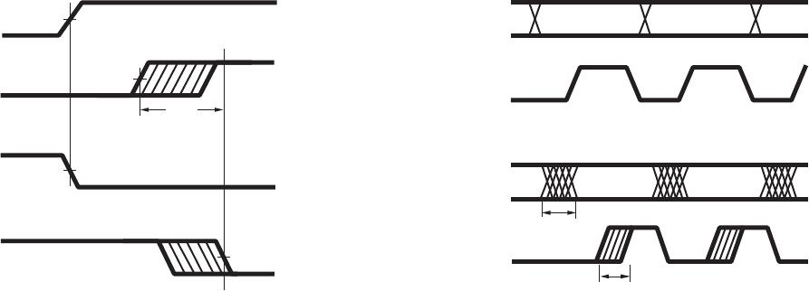
Figure 15. Propagation delay skew waveform Figure 16. Parallel data transmission example
Pulse-width distortion (PWD) is the dierence between
t
PHL
and t
PLH
and often determines the maxi mum data
rate capability of a transmission system. PWD can be
expressed in percent by dividing the PWD (in ns) by
the minimum pulse width (in ns) being trans mitted.
Typically, PWD on the order of 20 - 30% of the minimum
pulse width is tolerable. The PWD specication for the
HCPL-x710 is 8 ns (10%) maximum across recommend-
ed operating condi tions. 10% maximum is dictated
by the most stringent of the three eldbus standards,
PROFIBUS.
Propagation delay skew, t
PSK
, is an important parameter
to con sider in parallel data applications where synchro-
nization of signals on parallel data lines is a concern. If
the parallel data is being sent through a group of op-
tocouplers, dierences in propagation delays will cause
the data to arrive at the outputs of the optocouplers at
dierent times. If this dierence in propagation delay
is large enough it will determine the maximum rate at
which parallel data can be sent through the optocou-
plers.
Propagation delay skew is dened as the dier-
ence between the minimum and maximum propa-
gation delays, either t
PLH
or t
PHL
, for any given group
of optocoup lers that are operating under the same
conditions (i.e., the same drive current, supply volt age,
output load, and operating temperature). As illustrated
in Figure 15, if the inputs of a group of optocouplers
are switched either ON or OFF at the same time, t
PSK
is
the dierence between the shortest propagation delay,
either t
PLH
or t
PHL
, and the longest propagation delay,
either t
PLH
or t
PHL
.
As mentioned earlier, t
PSK
can determine the maximum
parallel data transmission rate. Figure 16 is the timing
diagram of a typical parallel data application with both
the clock and data lines being sent through the opto-
couplers. The gure shows data and clock signals at the
inputs and outputs of the optocouplers. In this case, the
data is assumed to be clocked o of the rising edge of
the clock.
Propagation delay skew repre sents the uncertain-
ty of where an edge might be after being sent
through an optocoupler. Figure 16 shows that there
will be uncertainty in both the data and clock lines.
These two areas of uncertainty must not overlap;
otherwise, the clock signal might arrive before all of
the data outputs have settled, or some of the data
outputs may start to change before the clock signal
has arrived. From these considerations, the absolute
minimum pulse width that can be sent through op-
tocouplers in a parallel application is twice t
PSK
.
A cautious design should use a slightly longer pulse
width to ensure that any additional uncertainty in the
rest of the circuit does not cause a problem.
The HCPL-x710 optocouplers oer the advantage of
guaranteed specications for propagation delays,
pulse-width distortion, and propagation delay skew
over the recommended temperature, and power supply
ranges.
50%
50%
t
PSK
V
I
V
O
V
I
V
O
2.5 V,
CMOS
2.5 V,
CMOS
DATA
INPUTS
CLOCK
DATA
OUTPUTS
CLOCK
t
PSK
t
PSK