AT97SC3205T [SUMMARY DATASHEET]
Atmel-8883AS-TPM-AT97SC3205T-Datasheet-Summary_022014
3
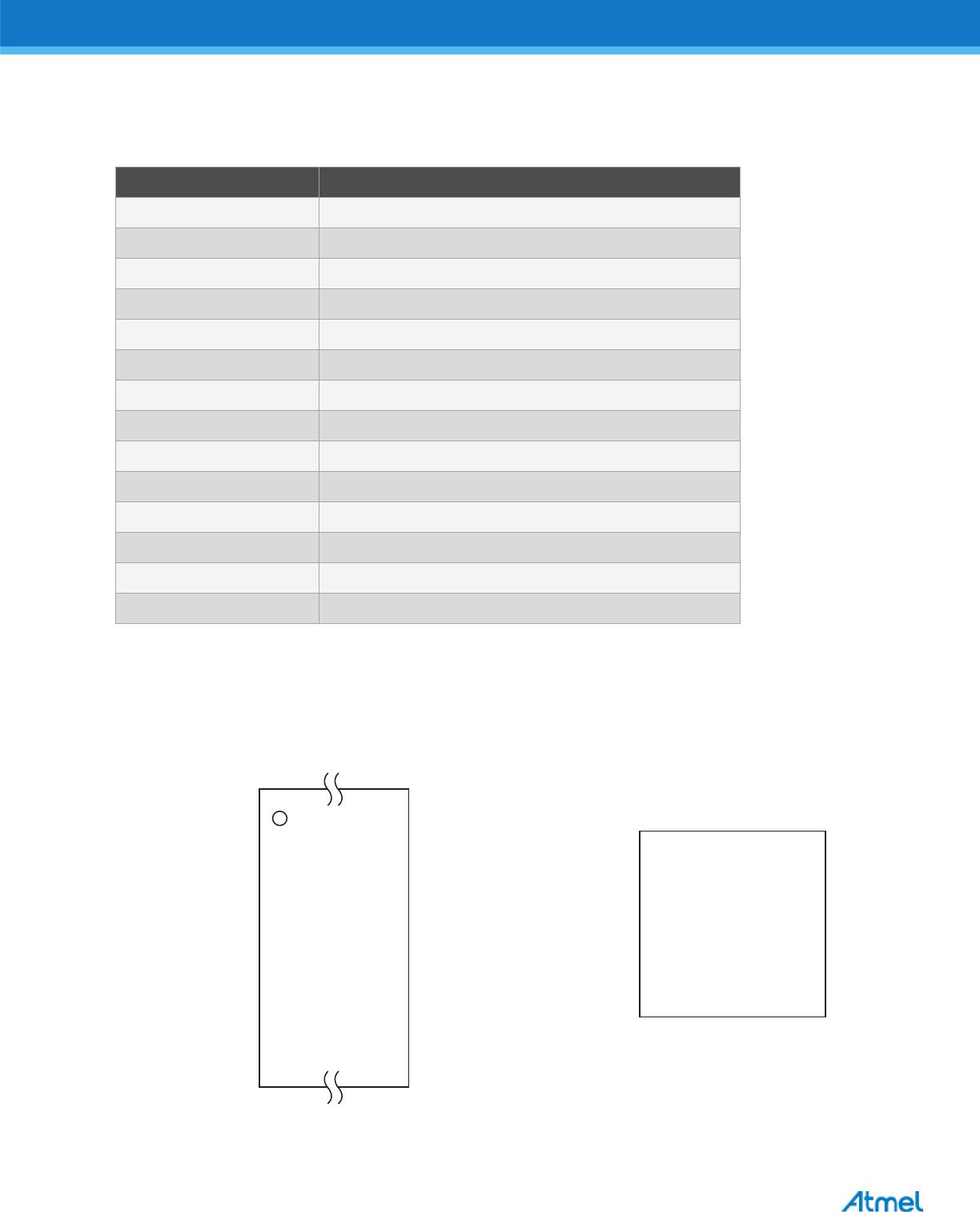
Table 1-2. Pin Descriptions
Pin Description
V
CC
Power Supply, 3.3V. Care should be taken to prevent excessive noise. Effective decoupling of the V
CC
inputs to the Atmel TPM is critical to assure consistently reliable operation over the lifetime of the
system. The Atmel recommendation is for a decoupling bypass capacitor within the range of 2200pF to
4700pF to be placed as close as possible <5mm to each of the V
CC
pins; located between each V
CC
pin
and the immediately adjacent GND pin. A 0.1μF decoupling bypass capacitor should be placed at the
node in which these V
CC
traces join as close as possible; <10mm to the TPM. In all cases, this bypass
capacitor should be closer than the next closest component. All capacitors should be of high quality with
dielectric ratings of X5R or X7R. A low-power state is automatically entered when the device is idle. No
further action is required by the system to enter low-power mode.
GND System Ground.
LRESET#
Reset Active-Low. Pulsing this signal low resets the internal state of the TPM and is equivalent to
removal/restoration of power to the device. The required minimum reset pulse width is 2μs. On power-
up, it is critical that Reset be kept active low until V
CC
stabilizes.
SM_DAT
I
2
C Data Input/Output. This pin serves as the Data Input/Output for the TPM. If one attempts to
communicate over the interface at close to the rated speed of 400kHz, the size of the pull-ups on
SM_DAT can be critical. A known value that functions properly at 400kHz is 800 on the SM_DAT line.
One may experiment with different pull-up values and/or reduce the clock rate if desired.
SM_CLK
I
2
C Clock Input. This pin serves as the Serial Clock Input to the TPM. If one attempts to communicate
over the interface at close to the rated speed of 400kHz, the size of the pull-ups on SM_CLK can be
critical. A known value that functions properly at 400kHz is 1.5K on the SM_CLK line. One may
experiment with different pull-up values and/or reduce the clock rate if desired.
The TPM communication stability is increased the closer to a 50% duty cycle on the SM_CLK signal
that can be provided. Although this becomes more critical at the rated speed of 400kHz, improvements
from a 50% duty cycle can result at lower speeds as well.
GPIO General Purpose Input/Output. If not used, tie high or low.
GPIO-Express-00
General Purpose Input/Output. Internal pull-up resistor. This pin is mapped to NV Index
TPM_NV_INDEX_GPIO_00 and serves as the GPIO-Express-00. Default TPM configuration: GPIO
Input. GPIO-Express-00 also serves as the XOR chain Output during I/O test mode. Since
GPIO-Express-00 has an internal pull-up it should be left floating if unused.
PP/GPIO
General Purpose Input/Output. Internal pull-down resistor. This pin is an indicator for hardware
physical presence; active high. Default TPM configuration: GPIO input. Since PP/GPIO has an internal
pull-down, it should be left floating if unused.
TestI
Test Input. TestI manufacturing test input disabled after manufacturing. Tie TestI to ground directly or
through a 4.7K resistor.
TestBI/GPIO/
XTAMPER
Test Input. The Atmel TPM does not support legacy addressing via the optional BADD implementation
of this pin.The TestBI pin serves as the XTAMPER pin or an additional GPIO pin, active high. (See the
application note, “Atmel Specific TPM Commands Reference Guide,” for details on XTAMPER
implementation). If unused, this pin should be tied to ground directly or through a 4.7K resistor.
TWI_Wakeup#
Low-Power Sleep Recovery. These two pins serve as the mechanism to allow the TPM to recover
from its low-power sleep state after receiving the Atmel Specific command TPM_DeepSleep (See Atmel
TPM Specific Commands document for further details). These pins must both be pulsed active low in
order to recover from the low-power sleep state. If unused, pin 7 can be left floating or tied to GND
either directly or through a 4.7K resistor. Pin 22 should be tied to GND or V
CC
either directly or through
a 4.7K resistor.