MFR25SFTF52-374K

Through-hole resisTors
FEATURES
Power Rating 1/6W, 1/4W, 1/2W, 1W, 2W, 3W
Resistance Tolerance ±0.5%, ±1%, ±5%
T.C.R. ±15ppm/°C, ±25ppm/°C, ±50ppm/°C, ±100ppm/°C
DERATING CURVE
For resistors operated in ambient temperatures above 70°C, power rating must be derated
in accordance with the curve below.
Rated Load (%)
Ambient Temperature (°C)
160140120100806040
100
80
60
40
20
20
70 155
°C
DIMENSIONS
Unit: mm
STYLE DIMENSION
Normal Miniature L øD H ød
MFR-12 MFR25S 3.4±0.3 1.9±0.2 28±2.0 0.45±0.05
MFR-25 MFR50S 6.3±0.5 2.4±0.2 28±2.0 0.55±0.05
MFR-50 MFR1WS 9.0±0.5 3.3±0.3 26±2.0 0.55±0.05
MFR100 MFR2WS 11.5±1.0 4.5±0.5 35±2.0 0.8±0.05
MFR200 MFR3WS 15.5±1.0 5.0±0.5 33±2.0 0.8±0.05
INTRODUCTION
The MFR Series Metal Film Resistors are
manufactured using a vacuum sputtering system
to deposit multiple layers of mixed metal
alloys and passivative materials onto a carefully
treated high grade ceramic substrate. After a
helical groove has been cut in the resistive layer,
tinned connecting leads of electrolytic copper
are welded to the end-caps. The resistors are
coated with layers of blue color lacquer.
Metal Film Resistors
General Type
Normal & Miniature Style [ MFR Series ]
ød
H L øD
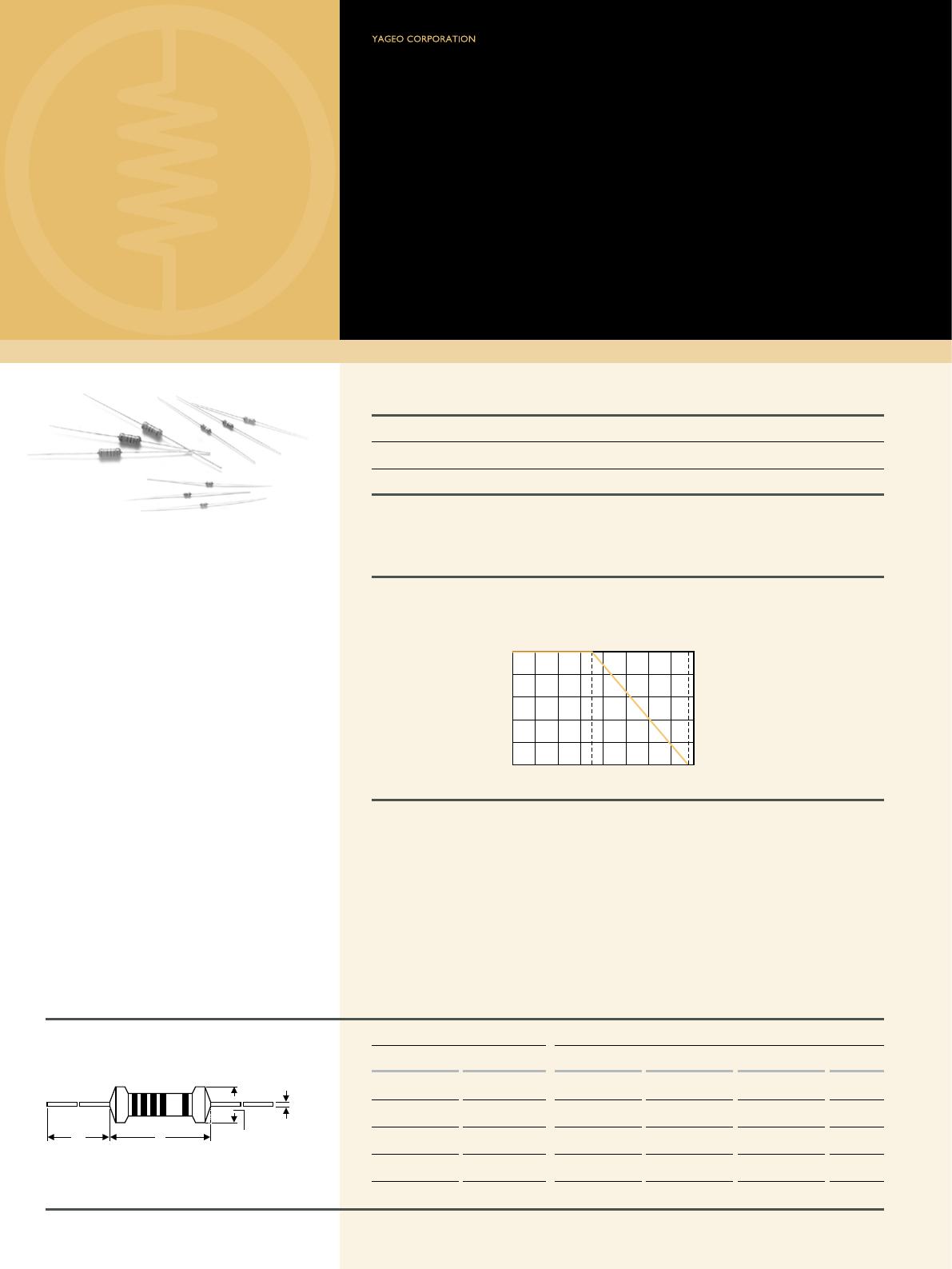
Note: RCWV(Rated Continuous Working Voltage) = Power Rating x Resistance Value or Max. working voltage listed above, whichever less.
Revision: 201304
Note:
5
ELECTRICAL CHARACTERISTICS
STYLE MFR-12 MFR25S MFR-25 MFR50S MFR-50 MFR1WS MFR100 MFR2WS MFR200 MFR3WS
Power Rating at 70°C 1/6W 1/4W 1/2W 1W 2W 3W
Maximum Working Voltage 200V 250V 300V 350V 400V 500V
Maximum Overload Voltage 400V 500V 600V 700V 800V 1,000V
Voltage Proof on Insulation 300V 400V 500V 700V 1,000V
Resistance Range 1Ω - 10MΩ & 0Ω for E24 & E96 series value
Operating Temp. Range -55°C to +155°C
Temperature Coefcient ±15ppm/°C, ±25ppm/°C, ±50ppm/°C, ±100ppm/°C
Note: Special value is available on request
ENVIRONMENTAL CHARACTERISTICS
PERFORMANCE TEST TEST METHOD APPRAISE
Short Time Overload IEC 60115-1 4.13 2.5 times RCWV for 5 Sec. ±0.25%+0.05Ω
Voltage Proof on Insulation IEC 60115-1 4.7 in V-block for 60 Sec., test voltage by type By type
Temperature Coefcient IEC 60115-1 4.8 -55°C to +155°C By type
Insulation Resistance IEC 60115-1 4.6 in V-block for 60 Sec. >10,000MΩ
Solderability IEC 60115-1 4.17 235±5°C for 3±0.5 Sec. 95% Min. coverage
Solvent Resistance of Marking IEC 60115-1 4.30 IPA for 5±0.5 Min. with ultrasonic
No deterioration of
coatings and markings
Robustness of Terminations IEC 60115-1 4.16 Direct load for 10 Sec. in the direction of the terminal leads ≥2.5kg (24.5N)
Periodic-pulse Overload IEC 60115-1 4.39 4 times RCWV 10,000 cycles (1 Sec. on, 25 Sec. off) ±1.0%+0.05Ω
Damp Heat Steady State IEC 60115-1 4.24 40±2°C, 90-95% RH for 56 days, loaded with 0.1 times RCWV ±1.5%+0.05Ω
Endurance at 70°C IEC 60115-1 4.25 70±2°C at RCWV for 1,000 Hr. (1.5 Hr. on, 0.5 Hr. off) ±1.5%+0.05Ω
Temperature Cycling IEC 60115-1 4.19 -55°C Room Temp. +155°C Room Temp. (5 cycles) ±0.75%+0.05Ω
Resistance to Soldering Heat IEC 60115-1 4.18 260±3°C for 10±1 Sec., immersed to a point 3±0.5mm from the body ±0.25%+0.05Ω
88
EXPLANATIONS OF ORDERING CODE
EXCEPTION:
• Cement series: • JPW series:
<Code 8>: Special packing style code
B: Bulk with wirewound or metal oxide sub-assembly for resistance value
W: Bulk with ceramic based wirewound sub-assembly for resistance value
M: Bulk with metal oxide sub-assembly for resistance value
F: Bulk with Fiberglass based wirewound sub-assembly for resistance value
<Code 10-12>: Without forming code
Example:
SQP500JB-10R
<Code 13-17>: without resistance value code
Example:
JPW-06-T-52-
-12
Code 4 - 6
Power Rating
-05 = ød0.5mm
-06 = ød0.6mm
-07 = ød0.7mm
-08 = ød0.8mm
-10 = ød1.0mm
-14 = ød1.4mm
-12 = 1/6W
-25 = 1/4W
25S = 1/4WS
-50 = 1/2W
50S = 1/2WS
100 = 1W
1WS = 1WS
200 = 2W
2WS = 2WS
204 = 0.4W
207 = 0.6W
300 = 3W
3WS = 3WS
3WM = 3WM
400 = 4W
500 = 5W
5WS = 5WS
5SS = 5WSS
700 = 7W
7WS = 7WS
10A = 10W
20A = 20W
30A = 30W
40A = 40W
50A = 50W
10S = 10WS
15A = 15W
25A = 25W
10B = 100W
25B = 250W
F
Code 7
Tolerance
P = ±0.02 %
A = ±0.05 %
B = ±0.1 %
C = ±0.25%
D = ±0.5 %
F = ±1 %
G = ±2 %
J = ±5 %
K = ±10 %
- = Base on Spec.
T
Code 8
Packing Style
T = Tape/Box
R = Tape/Reel
B = Bulk
F
Code 9
Temperature Coef-
cient of Resistance
- = Base on Spec.
A = ±5 ppm/°C
B = ±10 ppm/°C
C = ±15 ppm/°C
S = ± 20ppm/°C
D = ±25 ppm/°C
E = ±50 ppm/°C
F = ±100 ppm/°C
G = ±200 ppm/°C
H = ±250 ppm/°C
I = ±300 ppm/°C
J = ±350 ppm/°C
52-
Code 10 - 12
Forming Type
26- = 26mm
52- = 52.4mm
73- = 73mm
81- = 81mm
91- = 91mm
F = F Type
FK = FK Type
FKK = FKK Type
FFK = F-form Kink
M = M-Type Forming
MB = M-form W/at
MT = MT Type Forming
MR = MR Type
AV = AVIsert
PN = PANAsert
100R
Code 13 - 17
Resistance Value
0R1 = 0.1
100R = 100
10K = 10,000
10M = 10,000,000
MFR
Code 1 - 3
Series Name
See Index

MFR25SFTF52-374K

Mfr. #:
Manufacturer:
Yageo
Description:
Metal Film Resistors - Through Hole
Lifecycle:
New from this manufacturer.
Delivery:
DHL FedEx Ups TNT EMS
Payment:
T/T Paypal Visa MoneyGram Western Union