140 CRH
www.vishay.com
Vishay BCcomponents
Revision: 31-Jan-17
7
Document Number: 28396
For technical questions, contact: aluminumcaps1@vishay.com
THIS DOCUMENT IS SUBJECT TO CHANGE WITHOUT NOTICE. THE PRODUCTS DESCRIBED HEREIN AND THIS DOCUMENT
ARE SUBJECT TO SPECIFIC DISCLAIMERS, SET FORTH AT www.vishay.com/doc?91000
Note
• Unless otherwise specified, all electrical values in Table 6 apply
at T
amb
= 20 °C, P = 86 kPa to 106 kPa, RH = 45 % to 75 %
ORDERING EXAMPLE
Electrolytic capacitor 140 CRH series
220 μF / 50 V; ± 20 %
Nominal case size: 12.5 mm x 12.5 mm x 13 mm; taped on
reel
Ordering code: MAL214099111E3
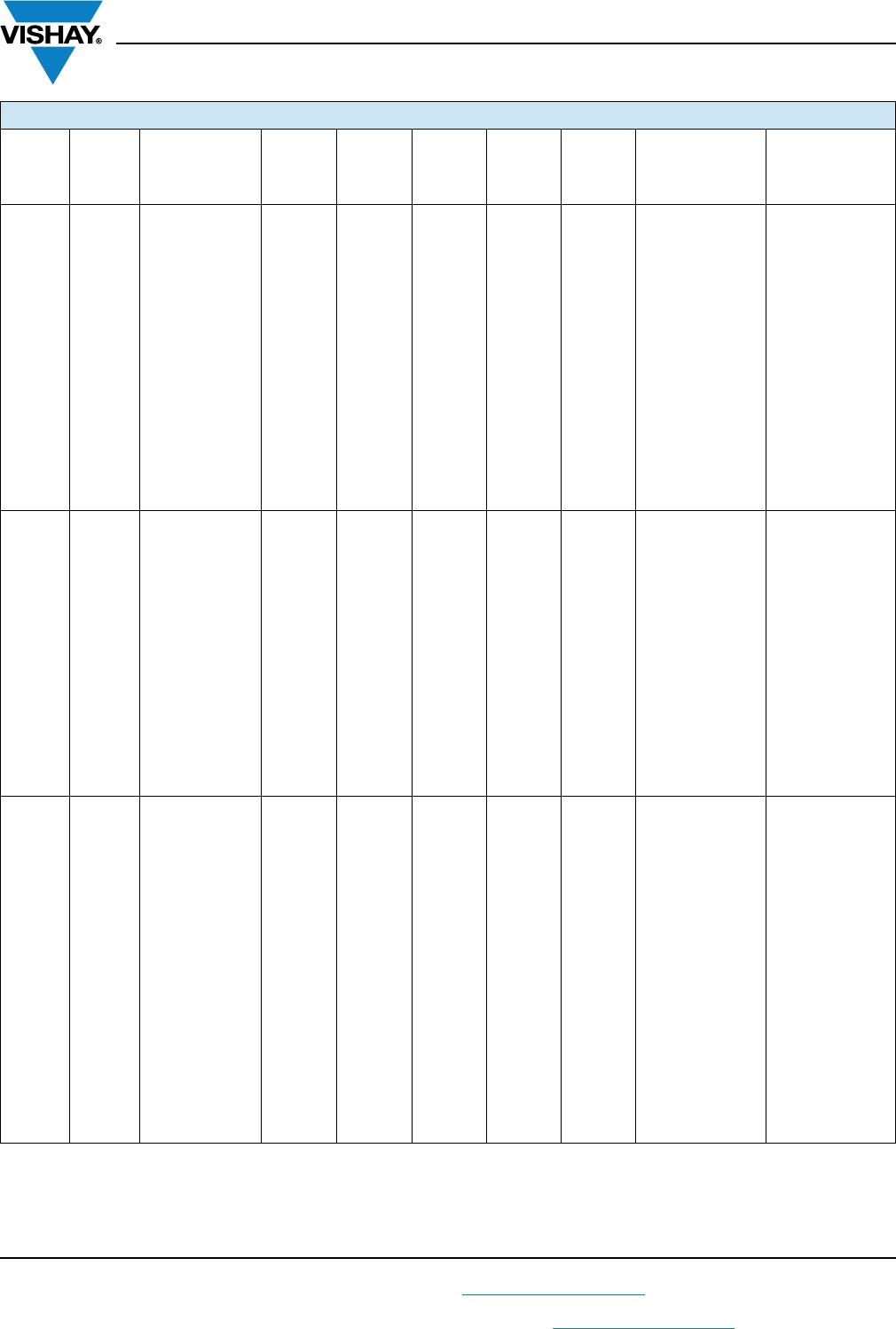
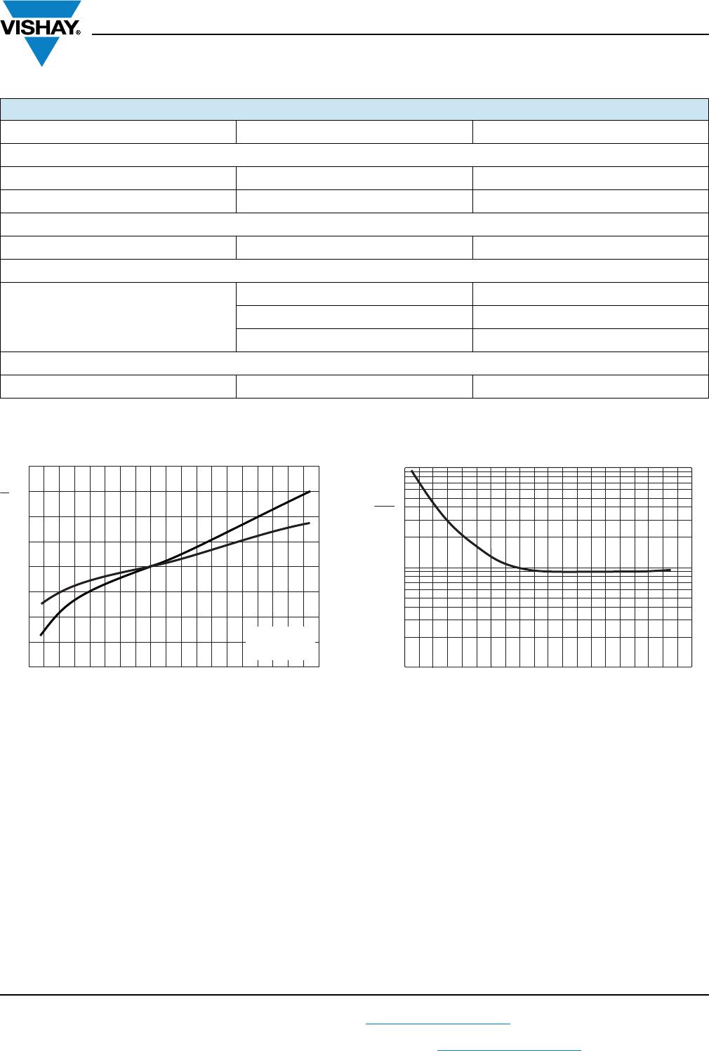
Table 6
ELECTRICAL DATA
SYMBOL DESCRIPTION
C
R
Rated capacitance at 100 Hz, tolerance ± 20 %
I
R
Rated RMS ripple current at 100 kHz, 125 °C
I
L2
Max. leakage current after 2 min at U
R
tan Max. dissipation factor at 100 Hz
Z Max. impedance at 100 kHz
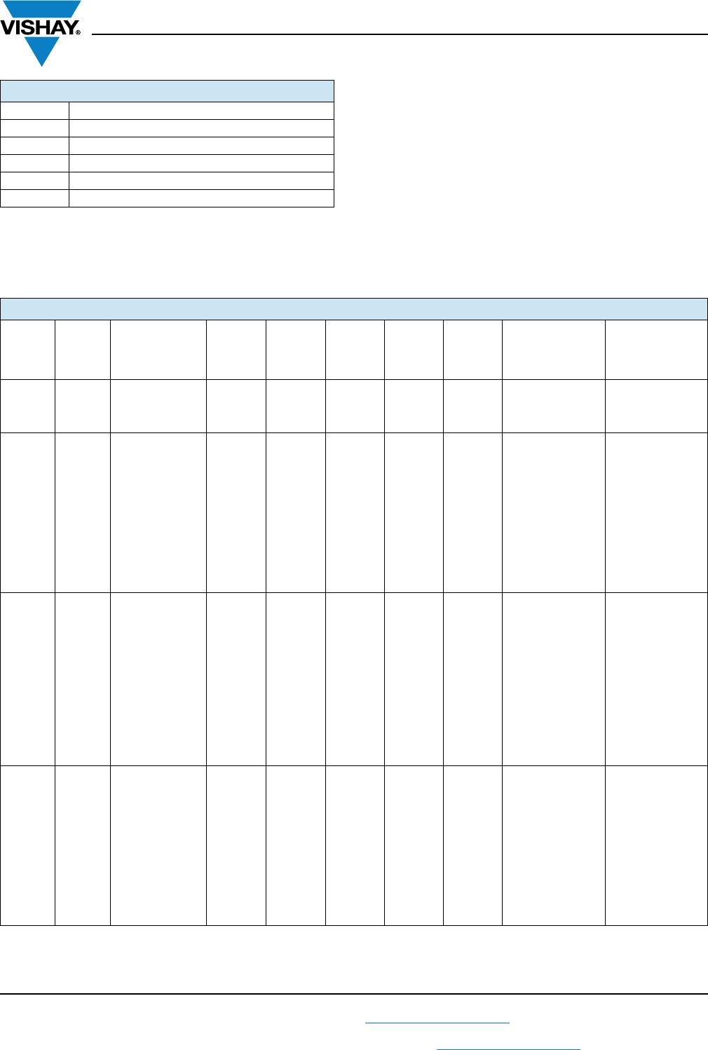
ELECTRICAL DATA AND ORDERING INFORMATION
U
R
(V)
C
R
(μF)
NOMINAL
CASE SIZE
L x W x H
(mm)
I
R
100 kHz
125 °C
(mA)
I
L2
2 min
(μA)
tan
100 Hz
Z
100 kHz
20 °C
()
LIFE
CODE
(3)
ORDERING
CODE
(1)
MAL2140...
ORDERING
CODE
(2)
MAL2140...
6.3
330 8 x 8 x 10 180 21 0.30 0.40 L1 97303E3 -
470 10 x 10 x 10 300 30 0.30 0.25 L1 97301E3 -
470 10 x 10 x 10 300 30 0.30 0.25 L1 - 99301E3
680 10 x 10 x 14 430 43 0.30 0.20 L1 97302E3 -
10
220 8 x 8 x 10 180 22 0.26 0.40 L1 97403E3 -
330 10 x 10 x 10 300 33 0.26 0.25 L1 97401E3 -
330 10 x 10 x 10 300 33 0.26 0.25 L1 - 99401E3
470 10 x 10 x 14 430 47 0.26 0.20 L1 97402E3 -
680 12.5 x 12.5 x 13 750 68 0.22 0.12 L2 97411E3 -
680 12.5 x 12.5 x 13 750 68 0.22 0.12 L3 - 99411E3
1000 12.5 x 12.5 x 16 900 100 0.22 0.09 L2 97412E3 -
1000 12.5 x 12.5 x 16 900 100 0.22 0.09 L4 - 99412E3
2200 16 x 16 x 16 1000 220 0.24 0.08 L5 - 99413E3
3300 16 x 16 x 21 1200 330 0.24 0.06 L5 - 99414E3
3300 18 x 18 x 16 1200 330 0.26 0.08 L5 - 99415E3
4700 18 x 18 x 21 1550 470 0.28 0.06 L5 - 99416E3
16
150 8 x 8 x 10 180 24 0.22 0.40 L1 97502E3 -
330 10 x 10 x 14 430 53 0.22 0.20 L1 97501E3 -
470 12.5 x 12.5 x 13 750 75 0.18 0.12 L2 97511E3 -
470 12.5 x 12.5 x 13 750 75 0.18 0.12 L3 - 99511E3
680 12.5 x 12.5 x 16 900 108 0.18 0.09 L2 97512E3 -
680 12.5 x 12.5 x 16 900 108 0.18 0.09 L4 - 99512E3
1000 16 x 16 x 16 1100 160 0.18 0.08 L5 - 99513E3
1000 16 x 16 x 21 1200 160 0.18 0.06 L5 - 99514E3
1500 16 x 16 x 16 1100 240 0.18 0.08 L5 - 99515E3
1500 18 x 18 x 16 1200 240 0.18 0.08 L5 - 99516E3
2200 16 x 16 x 21 1200 352 0.20 0.06 L5 - 99517E3
2200 18 x 18 x 21 1550 352 0.20 0.06 L5 - 99518E3
3300 18 x 18 x 21 1550 528 0.22 0.06 L5 - 99519E3
25
100 8 x 8 x 10 180 25 0.18 0.40 L1 97602E3 -
220 10 x 10 x 10 300 55 0.18 0.25 L1 97601E3 -
220 10 x 10 x 10 300 55 0.18 0.25 L1 - 99601E3
330 12.5 x 12.5 x 13 750 82 0.16 0.12 L2 97611E3 -
330 12.5 x 12.5 x 13 750 82 0.16 0.12 L3 - 99611E3
470 12.5 x 12.5 x 16 900 117 0.16 0.09 L2 97612E3 -
470 12.5 x 12.5 x 16 900 117 0.16 0.09 L4 - 99612E3
1000 16 x 16 x 16 1100 250 0.16 0.08 L5 - 99613E3
1000 16 x 16 x 21 1200 250 0.16 0.06 L5 - 99614E3
1500 16 x 16 x 21 1200 375 0.16 0.06 L5 - 99615E3
1500 18 x 18 x 16 1200 375 0.16 0.08 L5 - 99616E3
2200 18 x 18 x 21 1550 550 0.18 0.06 L5 - 99617E3
Notes
(1)
Standard reflow soldering profile, see Fig. 4 and Table 4
(2)
Advanced reflow soldering profile, according to JEDEC J-STD-020, see Fig. 5 and Table 5
(3)
Determines the applicable row in the table “Endurance Test Duration and Useful Life”