140 CRH
www.vishay.com
Vishay BCcomponents
Revision: 31-Jan-17
4
Document Number: 28396
For technical questions, contact: aluminumcaps1@vishay.com
THIS DOCUMENT IS SUBJECT TO CHANGE WITHOUT NOTICE. THE PRODUCTS DESCRIBED HEREIN AND THIS DOCUMENT
ARE SUBJECT TO SPECIFIC DISCLAIMERS, SET FORTH AT www.vishay.com/doc?91000
MOUNTING
The capacitors are designed for automatic placement on to
printed-circuit boards.
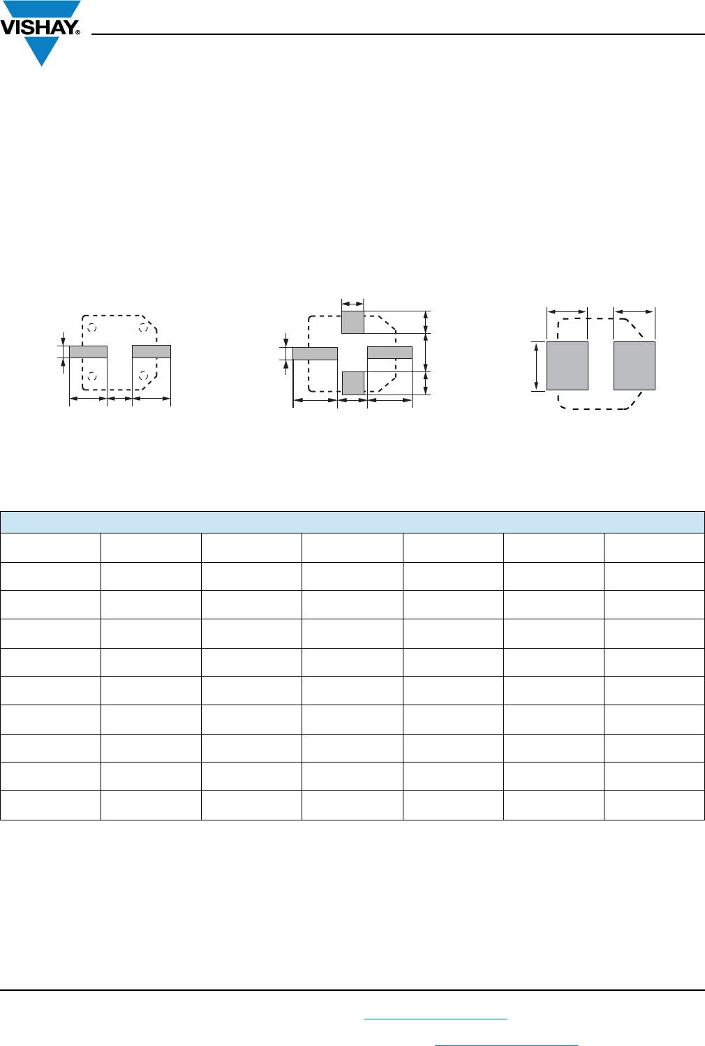
Optimum dimensions of soldering pads depend amongst
others on soldering method, mounting accuracy, print
layout and / or adjacent components.
For recommended soldering pad dimensions, refer to Fig. 3
and Table 3.
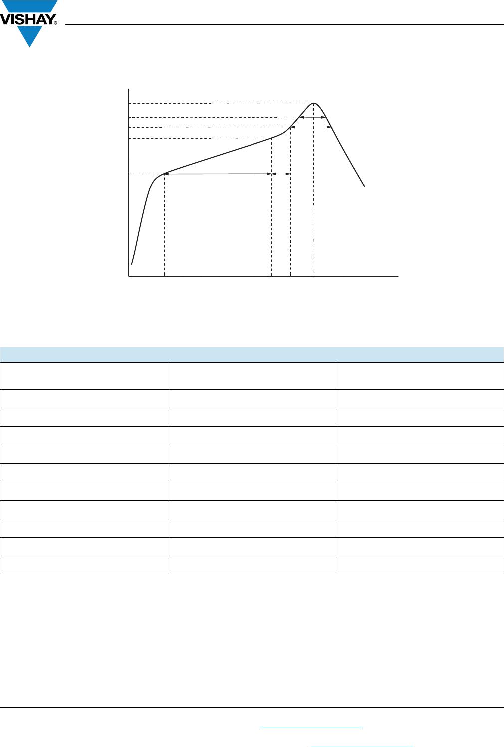
SOLDERING
Soldering conditions are defined by the curve, temperature
versus time, where the temperature is that measured on the
component during processing.
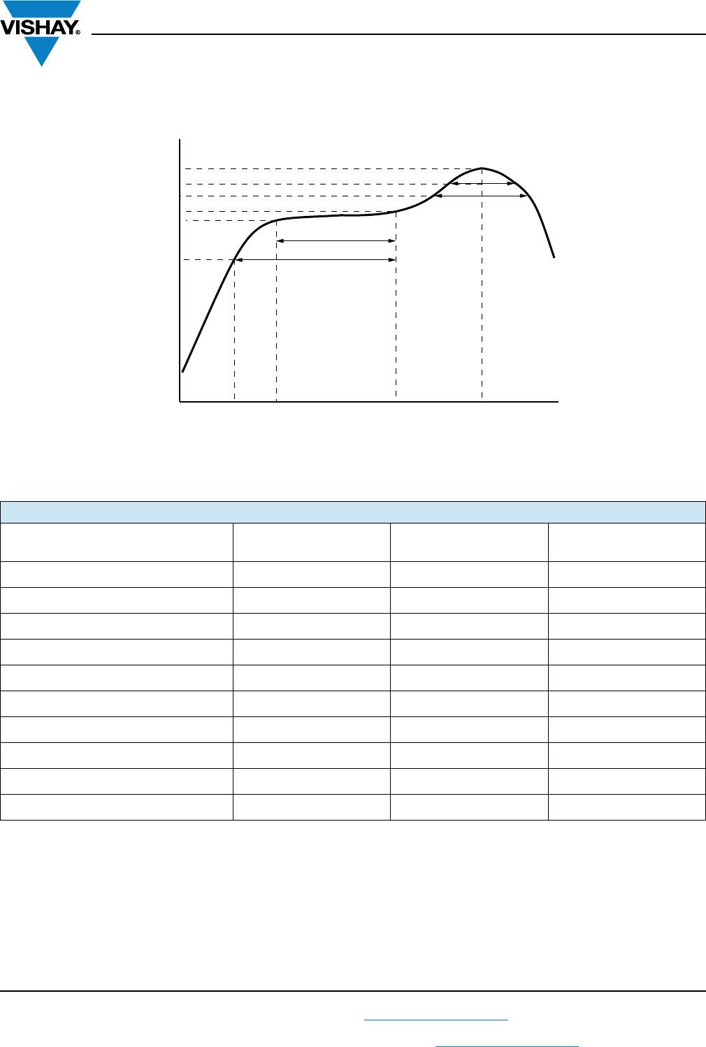
For maximum conditions refer to Fig. 4 or Fig. 5.
Any temperature versus time curve which does not exceed
the specified maximum curves may be applied.
As a general principle, temperature and duration shall be the
minimum necessary required to ensure good soldering
connections. However, the specified maximum curves
should never be exceeded.
Fig. 3 - Recommended soldering pad dimensions
Table 3
RECOMMENDED SOLDERING PAD DIMENSIONS in millimeters
CASE CODE a b c d e f
0810 4.4 2.5 3.0 - - -
1010 4.4 2.5 4.0 - - -
1014 4.4 2.5 4.0 - - -
1213 6.3 2.5 4.0 4.2 5.0 5.6
1216 6.3 2.5 4.0 4.2 5.0 5.6
1616 7.8 9.6 4.7 - - -
1621 7.8 9.6 4.7 - - -
1816 8.8 9.6 4.7 - - -
1821 8.8 9.6 4.7 - - -
aac
b
aac
b
e
d
f
d
Case size Ø D = 12.5 mm Case size Ø D ≥ 16 mmCase size Ø D ≤ 10 mm
a
a
b
c