LA5735M
No.A0588-4/7
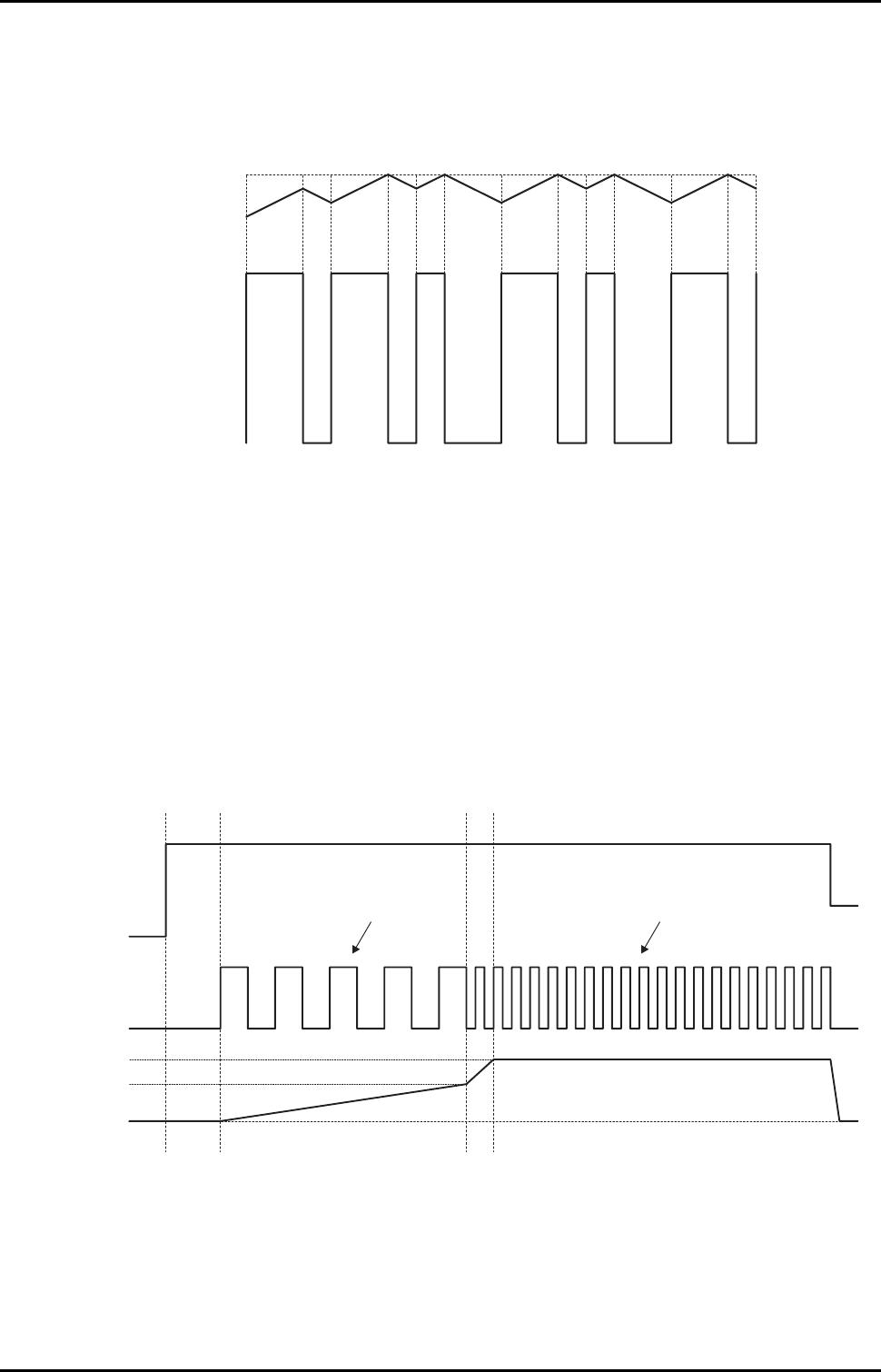
Choke coil L1
• Note that choke coil heating due to overload or load shorting may be a problem.
The inductance value can be determined from the following equation once the input voltage, output voltage, and
current ripple conditions are known. ∆IR indicates the ripple current value.
Reference example : V
IN
= 12V, V
OUT
= 5V, ∆IR = 150mA
L =
V
IN
- V
OUT
- Vsat
∆IR
× Ton
=
12 - 5.0 - 1.0
0.15
× 1.58 × 10
-6
≈ 68
µ
H
Ton =
T
((V
IN
- V
OUT
- Vsat)/(V
OUT
+ VF)) + 1
Toff = T - Ton
t : Switching repetition period················· 3.33µs is assumed for the calculation
VF : Schottky diode forward voltage ······ 0.4V is assumed for the calculation
• Inductance current : peak value
The ripple current peak value must be held within the rated current values for the inductor used.
Here, IRP is the peak value of the ripple current. IRP can be determined from the following equation.
Reference example : V
IN
= 12V, V
OUT
= 5V, I
OUT
= 0.5A, L = 68µH
IRP = I
OUT
+
V
IN
- V
OUT
- Vsat
2L
× Ton
= 0.5 +
12 - 5.0 - 1.0
2 × 68 × 10
-6
× 1.58 × 10
-6
≈ 0.57A
• Inductance current : ripple current value
Here ∆IR is the ripple current. ∆IR can be determined from the following equation.
If the load current becomes less than one half the ripple current, the inductor current will become discontinuous.
∆IR =
V
IN
- V
OUT
- Vsat
L
× Ton
=
12 - 5.0 - 1.0
68 × 10
-6
× 1.58 × 10
-6
≈ 0.15A
Diode D1
• A Schottky barrier diode must be used for this diode.
If a fast recovery diode is used, it is possible that the IC could be destroyed by the applied reverse voltage due to the
recovery and the on-state voltage.
• Diode current (peak current)
Applications must be designed so that the peak value of the diode current remains within the rated current of the
diode.
The peak value of the diode current will be the same current as the peak value of the inductor current.
• Repetitive peak reverse voltage
Applications must be designed so that the repetitive peak reverse voltage remains within the voltage rating of the
diode.
Here, V
RRM
is the repetitive peak reverse voltage. V
RRM
can be determined from the following equation.
V
RRM
≥ V
CC
Since noise voltage and other terms will be added in actual operation, the voltage handling capacity of the device
should be about 1.5 times that given by the above calculation.