Grayhill, Inc. • 561 Hillgrove Avenue • LaGrange, Illinois 60525-5997 • USA • Phone: 708-354-1040 • Fax: 708-354-2820 • www.grayhill.com
Rotary Switches
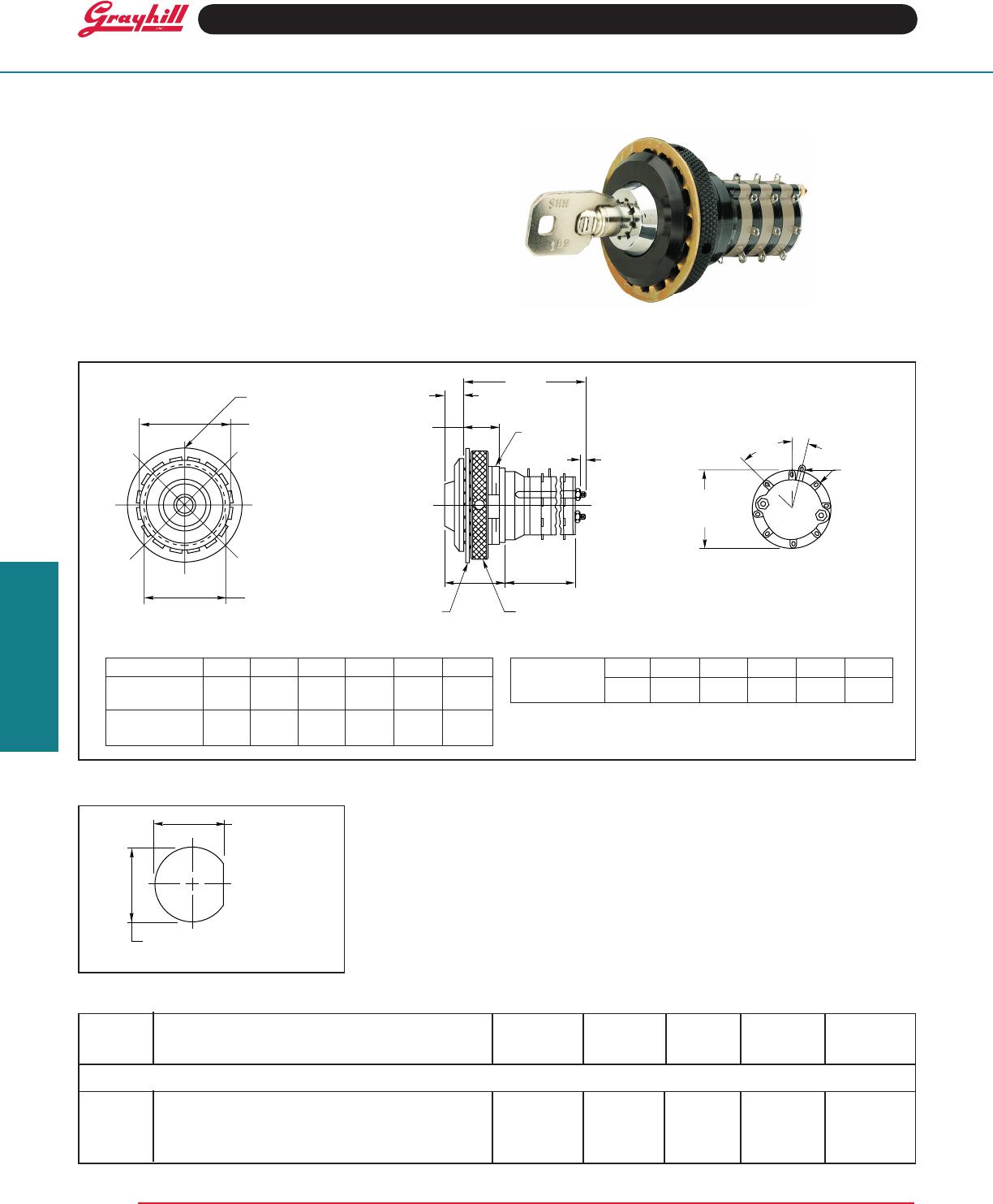
Keylock Rotary Switches
SWITCH SPECIFICATIONS
Electrical Characteristics
Industrial Grade Switch
Switching Current and Life
The load-life values indicate the number of
cyclesofoperationexpectedforthevoltage,
currentandtypeofload.Endoflifeisdened
using the resistance and breakdown failure
criteria listed below.
5Aat 115Vac,resistive
1Aat 6to28Vdc,resistive
2Aat 115Vac,inductive
Cycle of Operation: 360° rotation plus a
360°return
Test Conditions:25°C,68%relativehumidity,
atmospheric pressure
Life Expectancy:
Withloadsabove: 25,000cycles
Without load: 100,000 cycles
Contact Resistance:
Endoflife: lessthan 20 mΩ
Insulation Resistance:
(Between mutually insulated parts)
Initially: 50,000 MΩ
Breakdown Voltage:
(Between mutually insulated parts)
Initially: 1,000 Vac
Endoflife: 500 Vac
Carry Current: 10A; maximum temperature
rise20°C
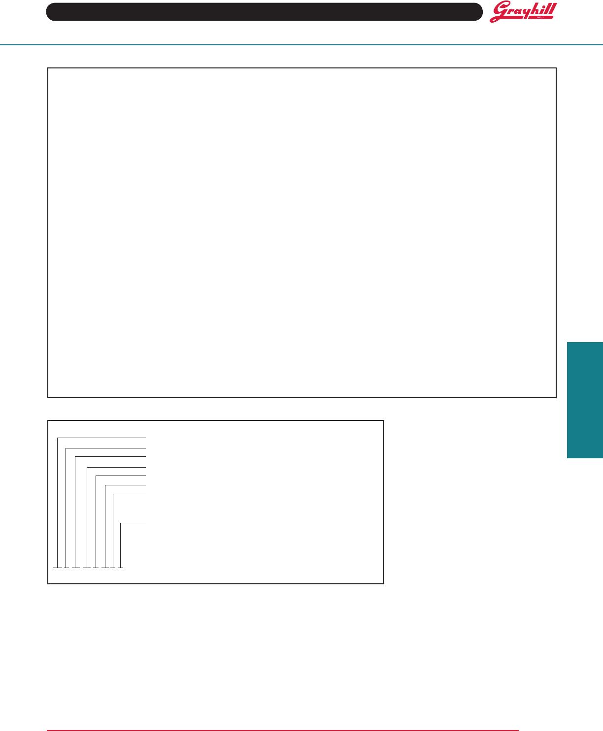
ORDERING INFORMATION
44 L 45-02-1-08N-F
Series
Style Letter: L
Angle of Throw:45°
Number of Decks: 01 thru 06 (per Choices chart)
Poles per Deck: 1 thru 4 (per Choices chart)
Positions per Pole: 02 thru 08 (per Choices chart)
Type of Contacts:
N = Non-shorting
S = Shorting (per Choices chart)
Stop Arrangement Suffix: (needed only for 1-pole switches
with
maximumpositions)
F=Fixedstopbetweenpositions8and1
*Leaveblankforcontinuousrotation
Available from your local Grayhill Distributor.
For prices and discounts, contact a local
Sales Ofce, an authorized local Distributor or
Grayhill.
Mechanical Characteristics
Switching Mode:
45°,1or2poles:Shortingornon-shorting
45°,3or4poles:Non-shorting
Type of Contact: Wiping contacts
Contact Force: greater than 150g
Number of Terminals:Switchesareprovided
withonlythenumberofterminalsneeded
Stop Strength: greater than 15 in-lbs (1.70
Nm)
Switching Torque: 8-115 in-ozs (28 to 230
mNm), depending on the number of poles,
numberofdecks,andangleofthrow
Additional Characteristics
Switchesof6ormoredeckshavelongerstuds
with extra mounting nuts for recommended
double end mount
Materials and Finishes: Switch
Switch Bases: Melamine per MIL–M–14, 4
Switch Bases:
Industrial Grade: Melamine per MIL–M–14
Military: Diallyl per MIL–M–14
Cover, Deck Separators, End Plate, and
Rotor Mounting Plate: Phenolic per
MIL–M–14
Shaft, Shaft Extension, Stop Arm, Stop
Washers, Rear Support Plate, Cover
Plate, Retaining Ring, Studs, Nuts: Stain-
less steel
Detent Balls: Steel, nickel-plated
Detent Springs: Tinned music wire
Rotor Contact, and Stator (Base) Con-
tacts: Silveralloy
Common Plate, and Common Terminal:
Brass, 300µinch,(7.6µm)silverplate
Base Terminals: Brass, tin plated