Bulk Metal
®
Foil Technology Ultra High Precision Trimming Potentiometers,
1
/
4
" Square, RJ26 Style, Designed to Meet or Exceed The Requirements of
MIL-PRF-39035, Char. H with a Smooth and Unidirectional Output
Accutrim™ 1240 (RJ26 Style)
Vishay Foil Resistors
Document Number: 63053 For any questions, contact: foil@vishaypg.com www.foilresistors.com
Revision: 23-Mar-10 1
INTRODUCTION
Vishay Foil precision trimmers have the Bulk Metal
®
Foil
resistive element which possesses a unique inherent
temperature and load life stability. Plus, their advanced
virtually back lash-free adjustment mechanism makes them
easy to set quickly and accurately and keeps the setting
exactly on target.
FEATURES
• Temperature coefficient of resistance (TCR):
± 10 ppm/°C. (- 55 °C to + 150 °C ref. at + 25 °C);
through the wiper
(3)
; ± 25 ppm/°C (see table 2 for
low values)
• A smooth and unidirectional resistance with
leadscrew adjustment
• Load life stability: 0.1 % typical ΔR, 1.0 % maximum ΔR
under full rated power at + 85 °C for 10 000 h
• Settability: 0.05 % typical; 0.1 % maximum
• Setting stability: 0.1 % typical; 0.5 % maximum, DSS
• Power rating: 0.25 W at + 85 °C
• Resistance range: 5 Ω to 10 kΩ
• Tolerance: ± 5 %, ± 10 %
• Electrostatic discharge (ESD) up to 25 000 V
• Terminal finish: gold plated (tin/lead finish is available on
request)
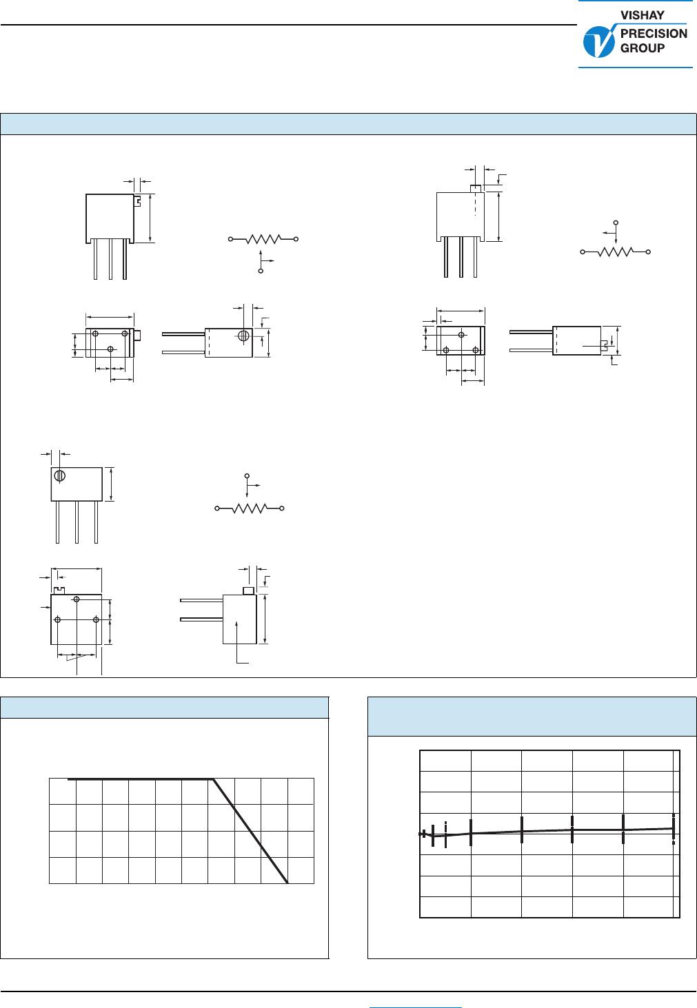
Note
• See Figure 1, next page
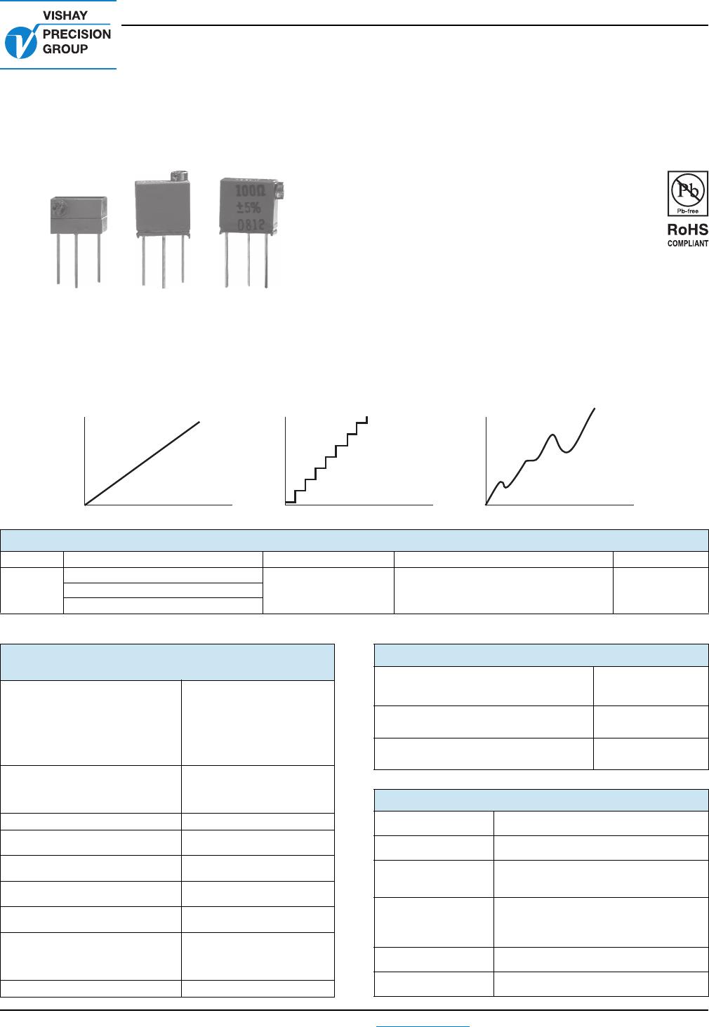
1240P 1240W 1240X
CERMET
Wiper Travel
Resistance
Wiper Travel
Resistance
BULK METAL
FOIL
WIREWOUND
Wiper Travel
Resistance
TABLE 1 - MODEL SELECTION
MODEL TERMINATION STYLE AVERAGE WEIGHT (g) POWER RATING at + 85 °C AMBIENT NO. OF TURNS
1240
W-edge mount, top adjust
0.4 0.25 W 21 ± 2X-edge mount, side adjust
P-horizontal mount, side adjust
TABLE 2 - 1240 (RJ26) SERIES
ELECTRICAL SPECIFICATIONS
Temperature Coefficient of
Resistance (TCR) 50 Ω to 10 kΩ
± 10 ppm/°C maximum
(- 55 °C to + 150 °C,
+ 25 °C ref.)
End-to-end
(2)
Temperature Coefficient of
Resistance 5, 10 and 20 Ω ± 20 ppm/°C
Through the wiper
(3)
± 25 ppm/°C
Stability
Load life at 10 000 h
End-to-end
(2)
0.1 % typical ΔR
1.0 % maximum ΔR
(under full rated power of
0.25 W at + 85 °C)
Power Rating
(4)
0.25 W at + 85 °C
Settability 0.05 % typical;
0.1 % maximum
Setting Stability 0.1 % typical;
0.5 % maximum
Contact Resistance
Variation - CRV (noise)
(5)
3 Ω typical;
10 Ω maximum
Hop-off 0.25 % typical;
1.0 % maximum
High-Frequency Operation
Rise time
Inductance
Capacitance
1.0 ns without ringing
0.08 µH typical
0.5 pF typical
Operating Temperature Range - 55 °C to + 150 °C
TABLE 3 - VALUES VS. TOLERANCES
STANDARD RESISTANCE VALUES
(in Ω)
STANDARD
TOLERANCE
5, 10 ± 10 %
20, 50, 100, 200, 500, 1K, 2K, 5K, 10K ± 5 %
TABLE 4 - MECHANICAL SPECIFICATIONS
Adjustment Turns
21 ±
2
Mechanical Stops
Wiper idles - no discontinuity
Internal
Terminations
All welded - no flux
Case Material
1240X - diallyl-phthalate: green (DAP)
1240W - diallyl-phthalate: green (DAP)
1240P - thermoplastic: black
Shaft Torque
3 oz. in. maximum
Backlash
0.005 % typical