QUAD HIFREQ Series
www.vishay.com
Vishay Vitramon
Revision: 07-Mar-17
1
Document Number: 45221
For technical questions, contact: mlccrf@vishay.com
THIS DOCUMENT IS SUBJECT TO CHANGE WITHOUT NOTICE. THE PRODUCTS DESCRIBED HEREIN AND THIS DOCUMENT
ARE SUBJECT TO SPECIFIC DISCLAIMERS, SET FORTH AT www.vishay.com/doc?91000
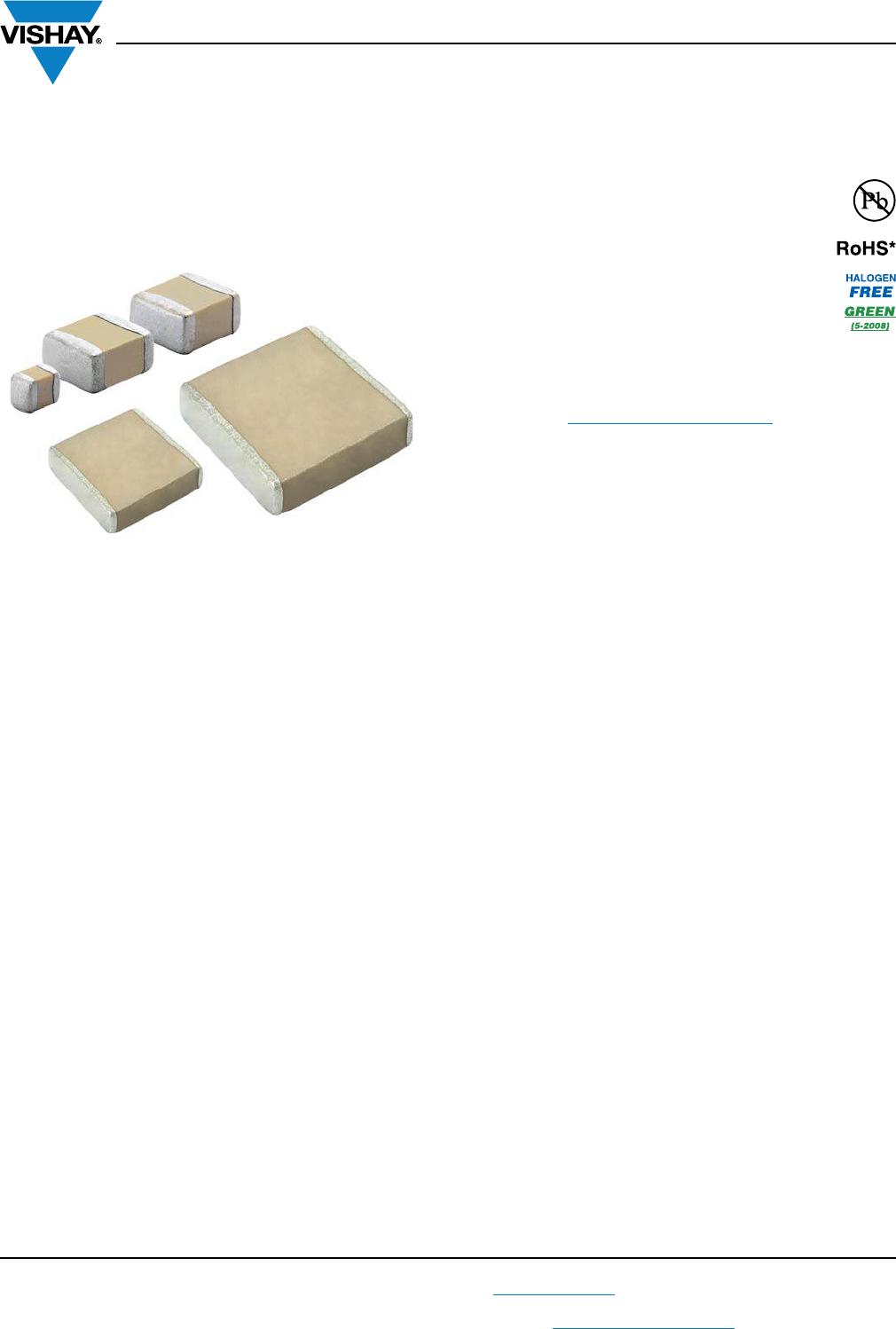
Surface Mount Multilayer Ceramic Capacitors
for RF Power Applications
FEATURES
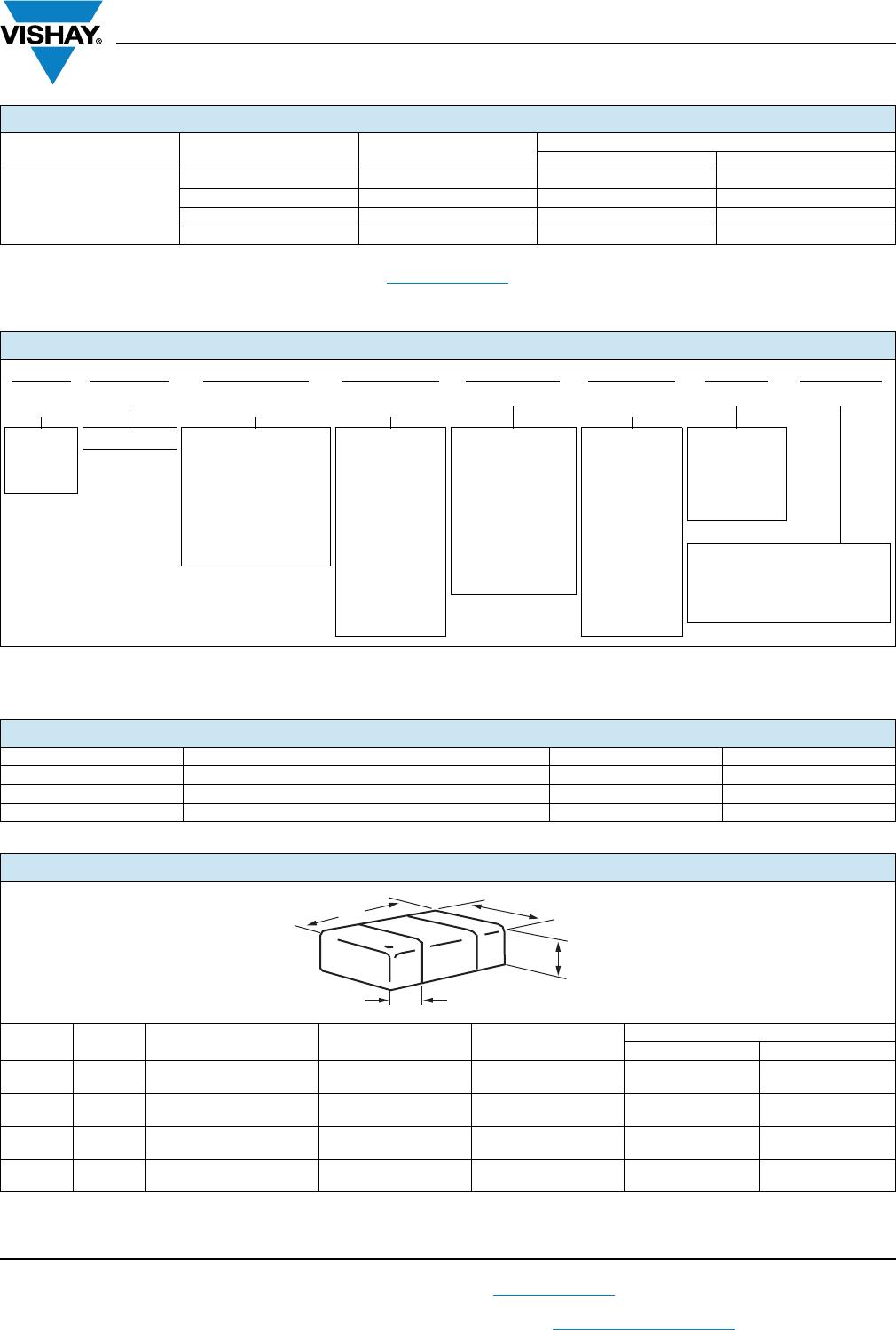
• Case size 0505, 1111, 2525, and 3838
• Ultra-stable, high Q dielectric material
• Lead (Pb)-free terminations code “X”
• Tin / lead termination code “L”
• Non-magnetic copper termination code “C”
• Reliable Noble Metal Electrode (NME) system
• High frequency
• Material categorization: for definitions of compliance
please see www.vishay.com/doc?99912
Note
*
This datasheet provides information about parts that are
RoHS-compliant and / or parts that are non RoHS-compliant. For
example, parts with lead (Pb) terminations are not RoHS-compliant.
Please see the information / tables in this datasheet for details
APPLICATIONS
• MRI coils and generators
• RF instruments
• Lasers, CATV, UHF / microwave RF power amplifiers
• Filter networks, timing circuits
• Mixers, oscillators impedance matching networks
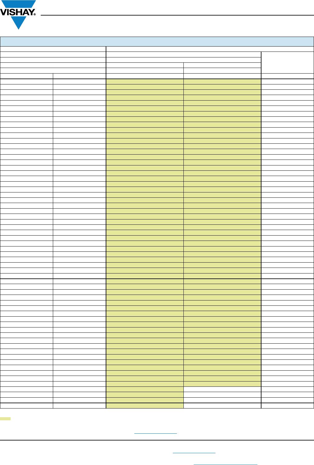
ELECTRICAL SPECIFICATIONS
Note
• Electrical characteristics at 25 °C unless otherwise specified
Operating Temperature:
full range: -55 °C to +125 °C
Extended Temperature (up to 500 V
DC
):
0505: -55 °C to 200 °C from 0.1 pF to 75 pF
1111: -55 °C to 200 °C from 0.2 pF to 200 pF
Capacitance Range:
0505: 0.1 pF to 100 pF
1111: 0.2 pF to 1000 pF
2525: 1.0 pF to 2700 pF
3838: 1.0 pF to 5100 pF
Voltage Rating:
0505: 200 V
DC
to 250 V
DC
1111: 300 V
DC
to 1500 V
DC
2525: 300 V
DC
to 3600 V
DC
3838: 500 V
DC
to 7200 V
DC
Temperature Coefficient of Capacitance (TCC):
C0G (D): 0 ppm/°C ± 30 ppm/°C from -55 °C to +125 °C with
zero (0) V
DC
applied
Dissipation Factor (DF):
C0G (D): 0.05 % max. at 1.0 V
RMS
and 1 MHz
for values 1000 pF
C0G (D): 0.05 % max. at 1.0 V
RMS
and 1 kHz
for values > 1000 pF
Aging Rate: 0 % maximum per decade
Insulation Resistance (IR):
at +25 °C and rated voltage 100 000 M minimum or
1000 F, whichever is less
at +125 °C and rated voltage 10 000 M minimum or
100 F, whichever is less
Dielectric Strength Test:
performed per method 103 of EIA-198-2-E.
Applied test voltages:
250 V
DC
-rated: min. 250 % of rated voltage
300 V
DC
-rated: min. 150 % of rated voltage
630 V
DC
- to 1000 V
DC
-rated: 150 % of rated voltage
1500 V
DC
and up: 120 % rated voltage
Available
Available
Available