DC872A

LTC4213
1
DESCRIPTION
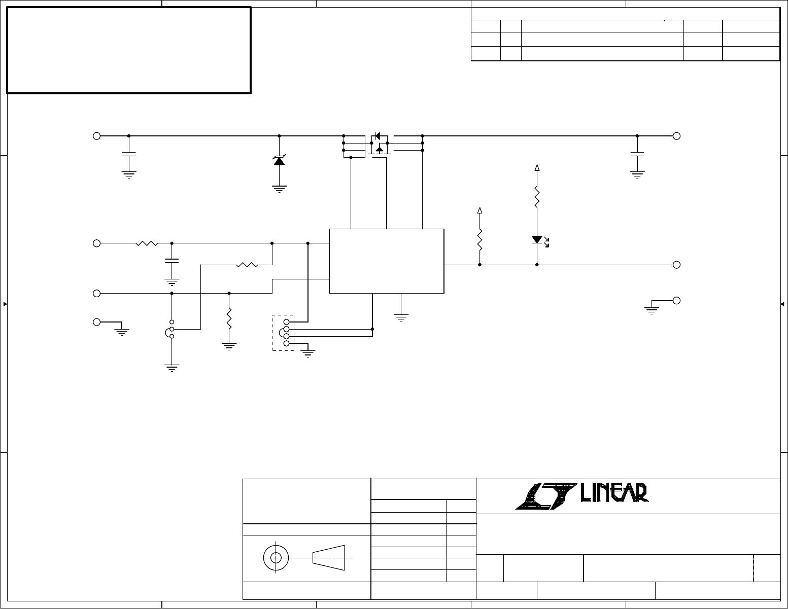
Demonstration circuit DC872A features the LTC4213
NoRsense Electronic Circuit Breaker, which provides
over-current protection without a sense resistor. The
Board allows evaluation of the LTC4213 over its full op-
erating voltage range, at all three over-current protection
levels and with ON and RESET functionality.
Design files for this circuit board are available. Call
the LTC factory.
, LTC and LT are registered trademarks of Linear Technology Corporation. ThinSOT and
PowerPath are trademarks of Linear Technology Corporation.
PERFORMANCE SUMMARY
Specification s are at T
A
= 2C
SYMBOL PARAMETER CONDITIONS MIN TYP MAX UNITS
V
CC
Supply Voltage Range
2.6 6.0 V
V
SENSEP
SENSEP Voltage Range V
SENSEP
V
CC
0 6.0 V
V
CC(URLR)
V
CC Undervoltage Lockout Release
V
CC
Rising
1.8 2.1 2.23 V
V
CB
Circuit Breaker Trip Voltage
V
CB
=V
SENSEP
-V
SENSEN
at slow comparator Trips
V
SENSEP
= V
CC
, I
OSEL
= 0V
V
SENSEP
= V
CC,
I
OSEL
= Floated
V
SENSEP
= V
CC,
I
OSEL
= V
CC
22.5
45
90
25
50
100
23
55
110
mV
V
CB(FAST)
Circuit Breaker Trip Voltage
V
CB(FAST)
=V
SENSEP
-V
SENSEN
at fast comparator
Trips
V
SENSEP
= V
CC
, I
OSEL
= 0V
V
SENSEP
= V
CC,
I
OSEL
= Floated
V
SENSEP
= V
CC,
I
OSEL
= V
CC
100
175
325
mV
mV
mV
I
GATE(UP)
Gate Pin Pull Up Current V
GATEN
= 0V, –50 -100 -150 µA
I
GATE(DN)
Gate Pin Pull Down Current
V
ON
=1V,
∆=
V
SENSEP
V
SENSEN
=200
mV,
V
GATE
= 8V
10 40 80 mA
V
ON(TH)
ON Pin High Threshold ON Rising, Gate Pulls Down 0.76 0.8 0.84 V
V
ON(RST)
ON Pin Reset Threshold ON Falling, Fault Reset, Gate Pulled Down
0.36
0.4 0.44
V
OPERATING PRINCIPLES
The LTC4213 is an Electronic Circuit Breaker that has a 0V
to 6.0V operating range and a 10V absolute maximum
operating voltage for the V
CC
pin. In low voltage applica-
tions where the rail voltage is lower than 2.6V, the V
CC
pin
must have a separate supply.
The circuit Breaker function is based on sensing the volt-
age across the drain and source of an external N-
channel MOSFET. The LTC4213 provides dual level over-
current protection. The slow comparator has 15µs re-
sponse time while the fast comparator trips in 1µs.
One of three Circuit Breaker thresholds, 25mV, 50mV, or
100mV is selected by connecting ISEL pin to GND, leav-
ing it floating, or connecting to Vcc, respectively. The cor-
responding fast comparator thresholds are 100mV,
175mV, and 325mV.
When the ON pin signal increases above 0.8V, the device
starts up and the GATE pulls up with a 100µA current
source. When the ON pin signal drops below 0.76V, the
GATE pulls down. To reset a circuit breaker fault, the ON
pin must go below 0.4V.
DEMO CIRCUIT
DC872A
QUICK START GUIDE
LTC4213
Electronic Circuit Breaker
5
5
4
4
3
3
2
2
1
1
D D
C C
B B
A A
VOUTVIN
GND
GND
READY
VCC
100mV
50mV
25mV
2.3V - 6.0V
VCC >/ = 2.3V
VCC >/ = VIN
0V - 6V
OPT
0V-6V@3.5A
EXT ON
ON from EXT
ON from Vcc
PROD2 06/22/05
REVISION HISTORY
DESCRIPTION DATE APPROVEDECO REV
2
DC872A
Wednesday, April 26, 2006
1
1
A
SCH, LTC4213CDDB, FAST CIRCUIT BREAKER
872A-2.DSN
NONE
MEI
12/02/04
SIZE
SCALE:
CAGE CODE
DWG NO
REV
SHEET
OF
FILENAME:
TITLE
CONTRACT NO.
APPROVALS
DATE
DRAWN
CHECKED
APPROVED
ENGINEER
DESIGNER
UNLESS OTHERWISE SPECIFIED
DIMENSIONS ARE IN INCHES
TOLERANCE ON ANGLE - - -
2 PLACES - - - 3 PLACES - - -
INTERPRET DIM AND TOL
PER ASME Y14.5M -1994
THIRD ANGLE PROJECTION
DO NOT SCALE DRAWING
TECHNOLOGY
1630 McCarthy Blvd.
Milpitas, CA 95035
Phone: (408)432-1900
Fax: (408)434-0507
Customer Notice:
Linear Technology has made a best effort to
design a circuit that meets customer-supplied specifications;
however, it remains the customers responsibility to verify proper
and reliable operation in the actual application, Component
substitution and printed circuit board layout may significantly
affect circuit performance or reliability. Contact Linear
Applications Engineering for assistance.
This circuit is proprietary to Linear Technology and supplied
for use with Linear Technology parts.
VCC
VCC
VCC
U1
LTC4213CDDB
1
2
3
4
5
6
7
8
READY
ON
ISEL
GND
GATE
SENSEN
SENSEP
VCC
R4
1K
E2
JP2
1
2
3
4
E7
C2
100uF
R3 33
R2
10K
E4
D1
RED
21
E5
R5
10K
C1
10uF
16V
E3
R1
18.2K
JP1
1 3
2
C3
100uF
E6
E1
Q1
Si4466DY
2
1
3
4
5
6
7
8
D2
SMAJ6.0A
12
LTC4213
2
QUICK START PROCEDURE
1.
Adjust electronic or passive load to 1A-1.2A cur-
rent and connect it between the Vout and GND
terminals.
2.
Connect a signal source (power supply, pulse
generator, etc.) between the ON and GND board
terminals and disable its output.
3.
Connect Power Supply output to VIN and GND. If
the power supply voltage is between 2.6V and 6V,
connect the Vcc terminal to Vin. If the power sup-
ply voltage is lower than 2.6V use an additional
voltage source for Vcc.
4.
Figure 1 illustrates DC872A connection with ex-
ternal equipment.
5.
Install current level selection jumper in the 25mV
position.
6.
Activate ON signal source and observe output
voltage transient.
7.
Increase the load to 2.0-2.5A and observe circuit
breaker performance.
8.
Repeat 5 and 6 with current level selection
jumper the 50mV and 100mV positions and corre-
sponding loads of 3.8-4.2A and 7.0-7.5A.

DC872A

Mfr. #:
Manufacturer:
Analog Devices Inc.
Description:
Other Development Tools LTC4213CDD Demoboard - Electronic Circui
Lifecycle:
New from this manufacturer.
Delivery:
DHL FedEx Ups TNT EMS
Payment:
T/T Paypal Visa MoneyGram Western Union

Products related to this Datasheet