mlcc_prec-P4
mlcc_prec_e-01
■ PRECAUTIONS
* This catalog contains the typical specification only due to the limitation of space. When you consider the purchase of our products, please check our specification.
For details of each product (characteristics graph, reliability information, precautions for use, and so on), see our Web site (http://www.ty-top.com/) or CD catalogs.
Precautions on the use of Multilayer Ceramic Capacitors
5. Cleaning
Precautions
◆Cleaning conditions
1. W
hen PCBs are cleaned after capacitors mounting, please select the appropriate cleaning solution in accordance with the intended use of the cleaning.(e.g.
to
remove soldering flux or other materials from the production process.)
2. Cleaning condition shall be determined after it is verified by using actual cleaning machine that the cleaning pr
ocess does not affect capacitor's characteristics.
Technical
consider-
ations
1. T
he use of inappr
opriate cleaning solutions can cause foreign substances such as flux residue to adhere to capacitors or deteriorate their outer coating, resulting in
a degradation of the capacitor's electrical properties (especially insulation r
esistance).
2. Inappropriate cleaning conditions (insuf
ficient or excessive cleaning) may adversely affect the performance of the capacitors.
In the case of ultrasonic cleaning, too much power output can cause excessive vibration of PCBs which may lead to the cracking of capacitors or the soldered
portion, or decrease the terminal electrodes' str
ength. Therefore, the following conditions shall be carefully checked;
Ultrasonic output : 20 W/ℓ or less
Ultrasonic frequency : 40 kHz or less
Ultrasonic washing period : 5 min. or less
6. Resin coating and mold
Precautions
1. With
some type of resins, decomposition gas or chemical reaction vapor may remain inside the resin during the hardening period or while left under normal stor-
age conditions resulting in the deterioration of the capacitor's performance.
2. When
a resin's hardening temperature is higher than capacitor's operating temperature, the stresses generated by the excessive heat may lead to damage or
destruction of capacitors.
T
he use of such r
esins, molding materials etc. is not recommended.
7. Handling
Precautions
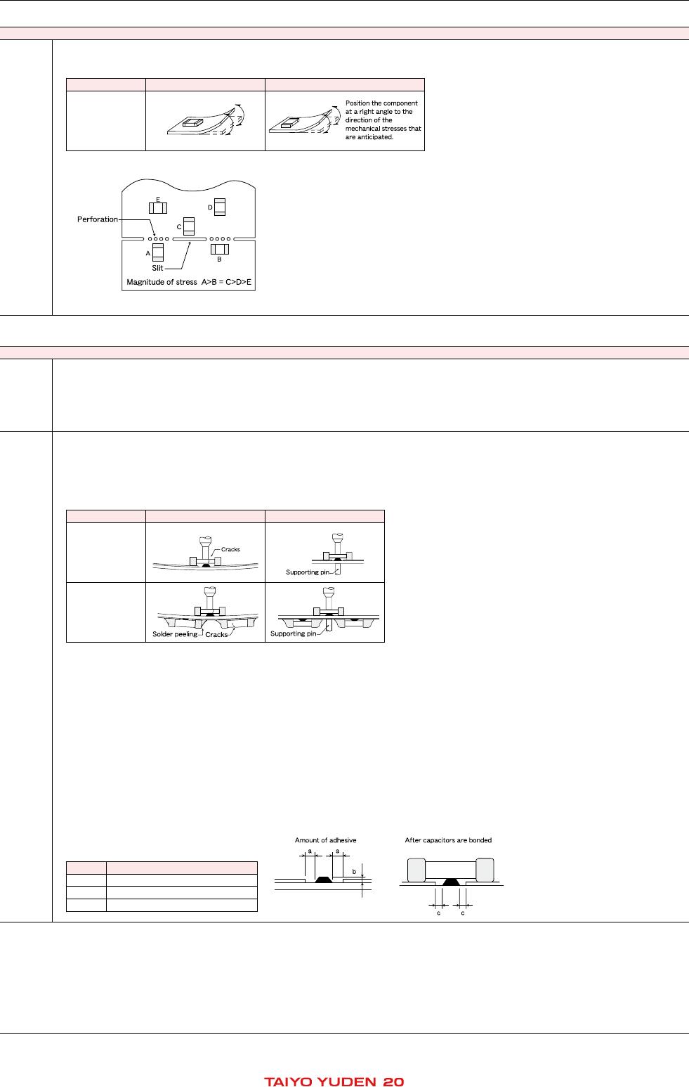
◆Splitting of PCB
1.
W
hen PCBs are split after components mounting, care shall be taken so as not to give any stresses of deflection or twisting to the board.
2. Boar
d separation shall not be done manually, but by using the appropriate devices.
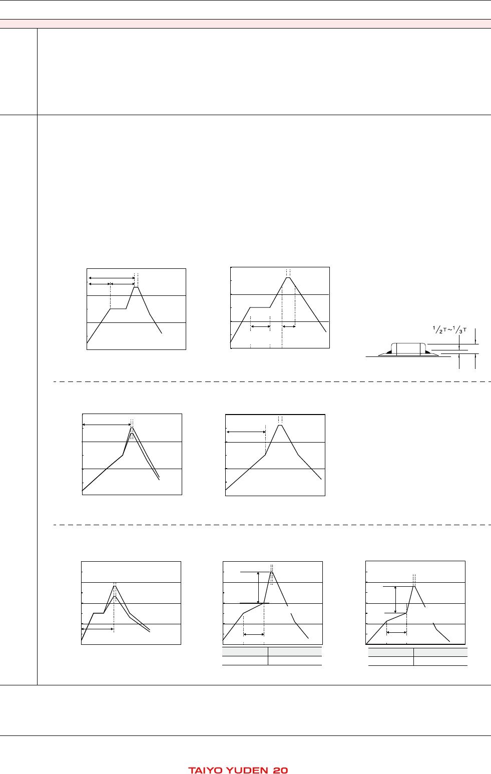
◆Mechanical considerations
Be car
eful not to subject capacitors to excessive mechanical shocks.
(1
)If ceramic capacitors are dropped onto a floor or a har
d surface, they shall not be used.
(2)Please be careful that the mounted components do not come in contact with or bump against other boards or components.
8.
Storage conditions
Precautions
◆Storage
1.
To maintain the solderability of terminal electrodes and to keep packaging materials in good condition, care must be taken to control temperature and humidity in
the storage area. Humidity should especially be kept as low as possible.
・Recommended conditions
A
mbient temperature : Below 30℃
Humidity : Below 70% RH
The
ambient temperature must be kept below 40℃.
Even under ideal storage conditions, solderability of capacitor is deteriorated as time passes, so capaci-
tors shall be used within 6 months from the time of delivery.
・Ceramic chip capacitors shall be kept wher
e no chlorine or sulfur exists in the air.
2.
The capacitance values of high dielectric constant capacitors will gradually decrease with the passage of time, so car
e shall be taken to design circuits . Even if
capacitance value decreases as time passes, it will get back to the initial value by a heat treatment at 150
℃ for 1hour.
Technical
consider-
ations
If c
apacitors
are stored in a high temperature and humidity environment, it might rapidly cause poor solderability due to terminal oxidation and quality loss of taping/
packaging materials. For
this reason, capacitors shall be used within 6 months from the time of delivery. If exceeding the above period, please check solderability be-
fore using the capacitors.
※RCR-2335B(
Safety Application Guide for fixed ceramic capacitors for use in electronic equipment)is published by JEIT
A.
Please check the guide regarding pr
ecautions for deflection test, soldering by spot heat, and so on.