Design and specifications are each subject to change without notice. Ask factory for the current technical specifications before purchase and/or use.
Should a safety concern arise regarding this product, please be sure to contact us immediately.
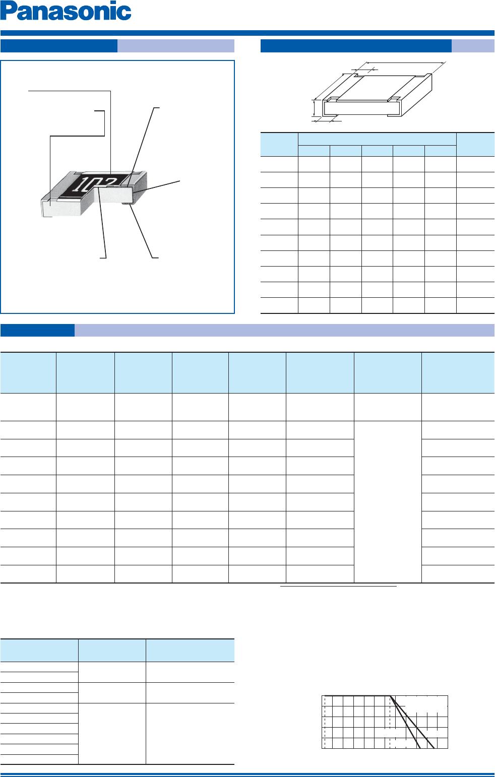
Thick Film Chip Resistors
E
1
R
2
J
3
3
4
G
5
E
6
Y
7
J
8
1
9
0
10
2
11
V
12
Thick Film
Chip Resistors
Product Code
Size, Power Rating
01005
0201
0402
0603
0805
1206
1210
1812
2010
2512
XGN
1GN
2GE
3GE
6GE
8GE
14
12
12Z
1T
0.031 W
0.05 W
0.1 W
0.1 W
0.125 W
0.25 W
0.5 W
0.75 W
0.75 W
1 W
Power R.
Marking
Code
Y
✽
Nil
Marking
Value Marking on
black side
No marking
Resistance Tolerance
Code
J
0
Tolerance
±5 %
Jumper
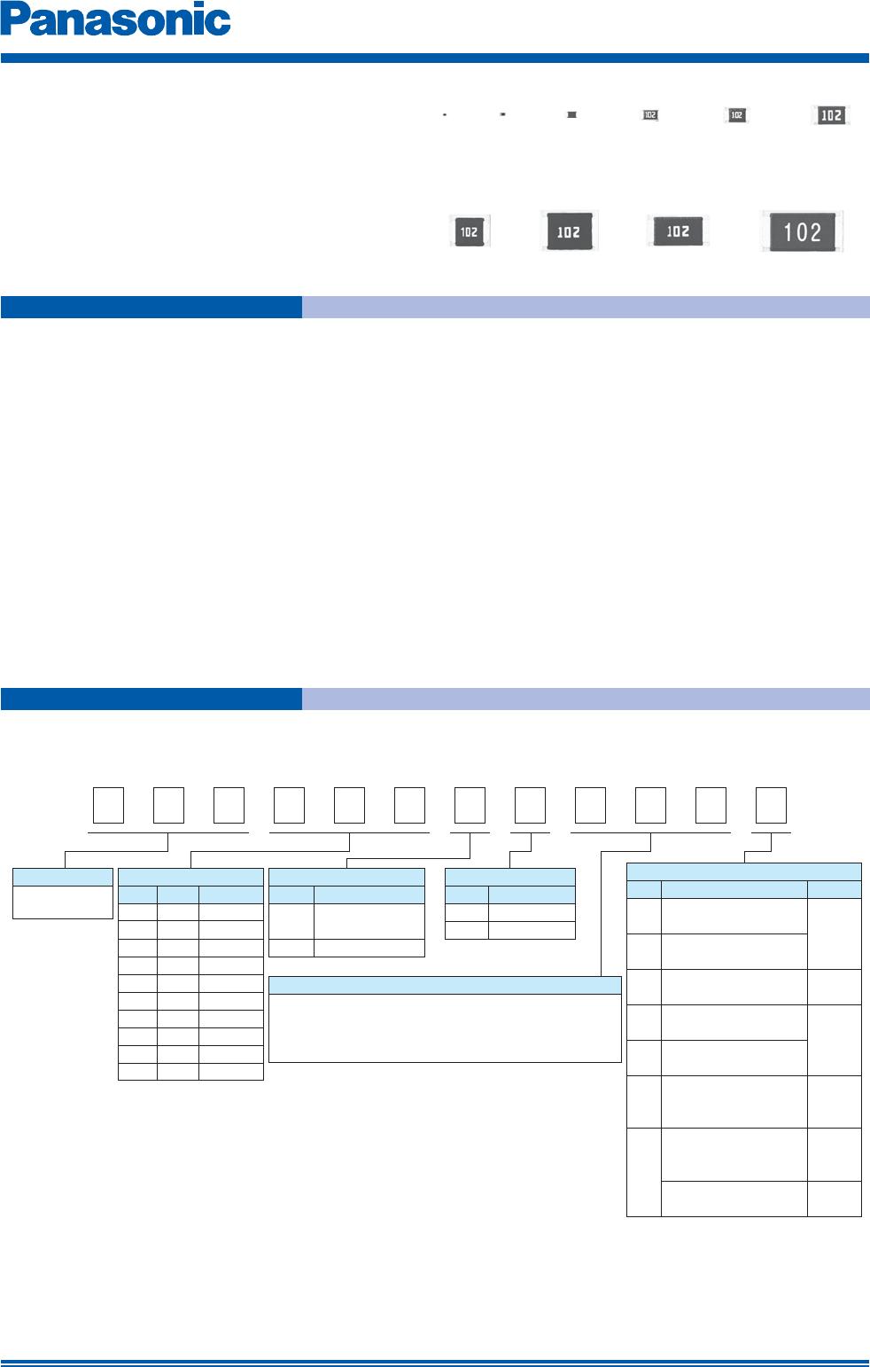
The first two digits are significant figures of resistance and
the third one denotes number of zeros following.
Decimal Point is expressed by R as 4.7 = 4R7.
Jumper is expressed by R00.
Resistance Value
Packaging Methods
Code
Y
U
Packaging Part No.
Embossed Carrier Taping
W4P1, 40,000 pcs.
Pressed Carrier Taping
W8P2, 20,000 pcs.
C
Pressed Carrier Taping
2 mm pitch, 15,000 pcs.
ERJXGN
X
Y
Punched Carrier Taping
2 mm pitch, 20,000 pcs.
U
Embossed Carrier Taping
4 mm pitch, 5,000 pcs.
Punched Carrier Taping
2 mm pitch, 10,000 pcs.
ERJ2GE
ERJ1GN
Embossed Carrier Taping
4 mm pitch, 4,000 pcs.
ERJ1T
ERJ14
ERJ12
ERJ12Z
Code
V
Punched Carrier Taping
4 mm pitch, 5,000 pcs.
ERJ3GE
ERJ6GE
ERJ8GE
Inch
Thick Film Chip Resistors
Type: ERJ XG, 1G, 2G, 3G, 6G,
8G, 14, 12, 12Z, 1T
Explanation of Part Numbers
Features
●
Small size and lightweight
●
High reliability
Metal glaze thick fi lm resistive element and three layers of electrodes
●
Compatible with placement machines
Taping packaging available
●
Suitable for both refl ow and fl ow sol der ing
●
Reference Standards
IEC 60115-8, JIS C 5201-8, EIAJ RC-2134B
●
AEC-Q200 qualifi ed (Exemption ERJXG)
●
RoHS compliant
✽ When omitted, the rest of the P/N factors shall be moved up respectively.
(Only XGN, 1GN, 2GE type)
■
As for Packaging Methods, Land Pattern, Soldering Conditions and Safety Precautions,
Please see Data Files
●
ERJXGN, 1GN, 2GE, 3GE, 6GE, 8GE, 14, 12, 12Z, 1T Type, ±5 %
Mar. 201505