LT6108-1/LT6108-2
22
610812fa
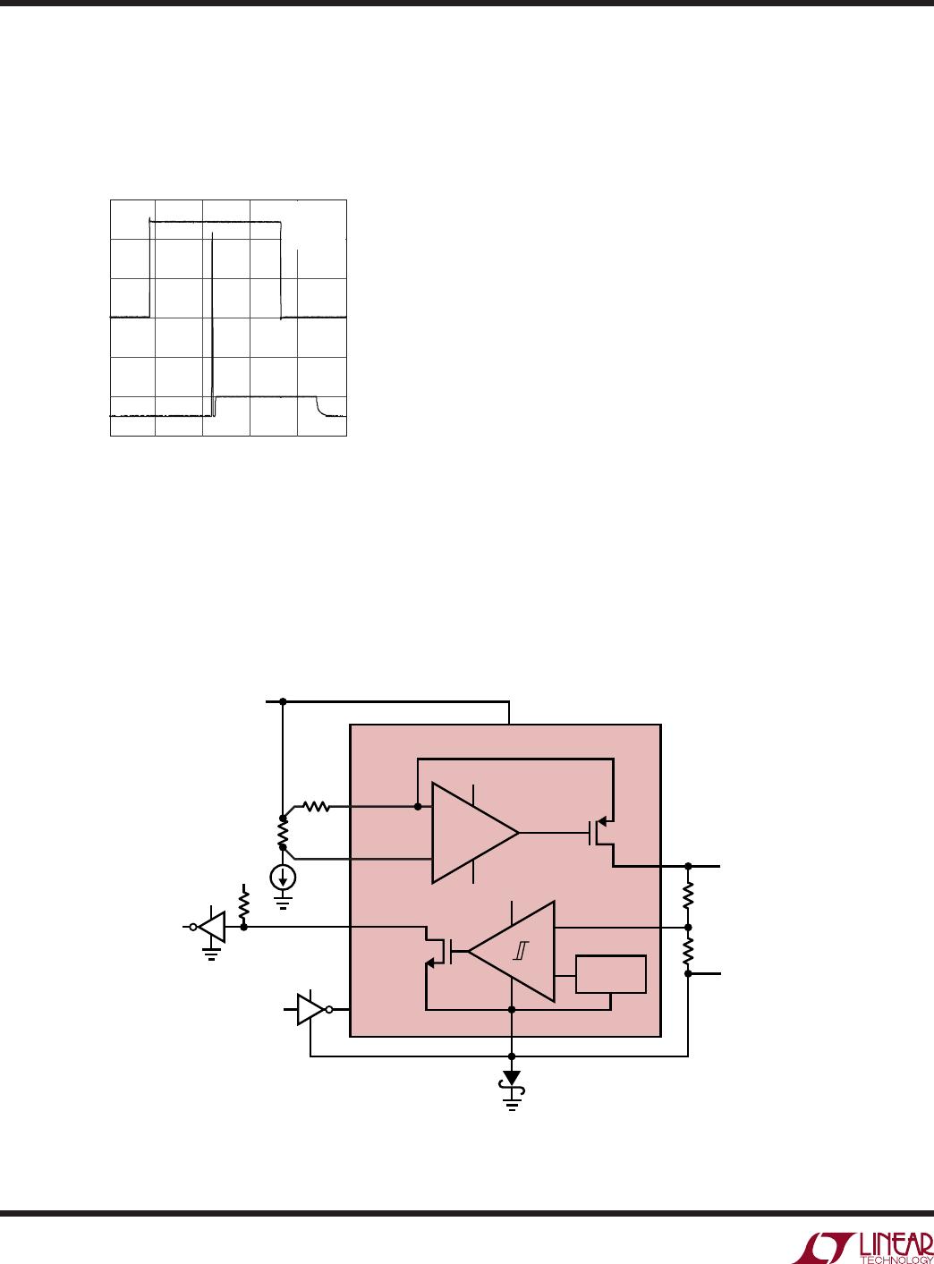
Figure 17. Amplifier Enable Response
current. Figure17 shows this behavior and the impact it has
on V
OUTA
. Circuitry connected to OUTA can be protected
from these transients by using an external diode to clamp
V
OUTA
, or a capacitor to filter V
OUTA
.
APPLICATIONS INFORMATION
Power Up
After powering on the LT6108-1, the comparator must
be reset in order to guarantee a valid state at its output.
Fast supply ramps may cause a supply current transient
during start-up as shown in the Typical Performance
Characteristics. This current can be lowered by reducing
the edge speed of the supply.
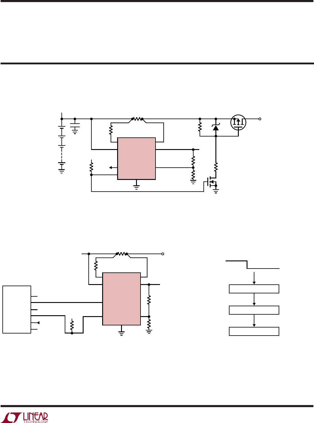
Reverse-Supply Protection
The LT6108 is not protected internally from external rever-
sal of supply polarity. To prevent damage that may occur
during this condition, a Schottky diode should be added
in series with V
(Figure 18). This will limit the reverse
current through the LT6108. Note that this diode will limit
the low voltage operation of the LT6108 by effectively
reducing the supply voltage to the part by V
D
.
Also note that the comparator reference, comparator
output and EN/RST input are referenced to the V
pin. In
order to preserve the precision of the reference and to
avoid driving the comparator inputs below V
, R2 must
connect to the V
pin. This will shift the amplifier output
voltage up by V
D
. V
OUTA
can be accurately measured
50µs/DIV
0V
V
EN/RST
2V/DIV
0V
V
OUTA
2V/DIV
610812 F17
V
+
= 60V
R
IN
= 100Ω
R
OUT
= 10k
+
V
+
V
+
V
INC
V
4
V
D
+
V
OUTA
+
610812 F18
OUTA 6
7
5
V
+
V
+
SENSEHI
LT6108-1
R
IN
R
SENSE
I
LOAD
V
DD
V
DD
SENSELO
OUTC3
EN/RST
2
1
8
400mV
REFERENCE
R3
R1
R2
V
DD
+
EN Pin (LT6108-2)
When this pin is pulled high, the LT6108-2 is enabled. When
the enable pin is pulled low for longer than 40µs typically,
the LT6108-2 will enter the shutdown mode.
Figure 18. Schottky Prevents Damage During Supply Reversal
LT6108-1/LT6108-2
23
610812fa
APPLICATIONS INFORMATION
TYPICAL APPLICATIONS
MCU Interfacing with Hardware Interrupts
SENSEHI SENSELO
OUTA
0.1Ω
V
+
100Ω
LT6108-1
V
TO LOAD
V
OUT
ADC IN
8.66k
1.33k
INC
V
+
EN/RST
OUTC
6
1
5
4
8
7
2
3
RESET
6108 TA03
10k
5V
V
OUT
/ADC IN
AtMega1280
PB0
PB1
PCINT2
PCINT3
ADC2
PB5
5
6
7
2
3
1
OVERCURRENT ROUTINE
RESET COMPARATOR
MCU INTERUPT
OUTC GOES LOW
5V
0V
610812 TA03b
Example:
The comparator is set to have a 300mA overcurrent
threshold. The MCU will receive the comparator output as
a hardware interrupt and immediately run an appropriate
fault routine.
Overcurrent Battery Fault Protection
SENSEHI SENSELO
OUTA
0.1Ω
R10
100Ω
LT6108-1
V
TO LOAD
V
OUT
9.53k
475Ω
0.8A
OVERCURRENT
DETECTION
INC
V
+
EN/RST
6
1
5
4
OUTC
8
7
10k
100k
6.2V*
IRF9640
2
5V
3
RESET
610812 TA02
100k
2N7000
*CMH25234B
+
+
+
+
10µF
12 LITHIUM
40V CELL STACK
differentially across R1 and R2. The comparator output
low voltage will also be shifted up by V
D
. The EN/RST pin
threshold is referenced to the V
pin. In order to provide
valid input levels to the LT6108 and avoid driving EN/RST
below V
the negative supply of the driving circuit should
be tied to V
of the LT6108.
LT6108-1/LT6108-2
24
610812fa
TYPICAL APPLICATIONS
Simplified DC Motor Torque Control
Power-On Reset or Disconnect Using TimerBlox
®
Circuit
The figure above shows a simplified DC motor control
circuit. The circuit controls motor current, which is pro-
portional to motor torque; the LT6108 is used to provide
current feedback to an integrator that servos the motor
current to the current set point. The LTC
®
6992 is used to
convert the output of the difference amp to the motors
PWM control signal.
SENSEHI SENSELO
OUTA
8 1
6
5
7
2
3
4
LT6108-1
V
9k
100k
2
3
7
LTC6246
4
6
1
3
6
IRF640
5V
1N5818
0.1Ω
V
MOTOR
5
4
2
0.47µF
V
OUT
CURRENT SET POINT (0V TO 5V)
1k
1M
610812 TA04
1k
78.7k
100k
280k
INC
V
+
EN/RST
OUTC
RESET
100µF
+
LTC6992-1
V
+
GND
5V
F
BRUSHED
DC MOTOR
(0A TO 5A)
MABUCHI
RS-540SH
MOD
SET
OUT
DIV
+
V
+
V
V
4
610812 TA06
V
+
400mV
REFERENCE
V
+
R
IN
100Ω
R
SENSE
I
LOAD
OUTA 6
INC 5
7
SENSEHI
LT6108-1
5V
SENSELO
OUTC
EN/RST
8
1
3
2
R1
9.53k
R2
499Ω
R7
10k
R4
1M
R5
487k
R6
30k
TRIG
C1
0.1µF
Q1
2N2222
OUT
GND V
+
SET DIV
LTC6993-3
5V
CREATES A DELAYED
10µs RESET PULSE
ON START-UP
OPTIONAL:
DISCHARGES C1
WHEN SUPPLY
IS DISCONNECTED
+
The LTC6993-3 provides a 10µs reset pulse to the LT6108-1.
The reset pulse is delayed by R4 and C1 whose time constant
must be greater than 10ms and longer than the supply
turn-on time. Optional components R6 and Q1 discharge
capacitor C1 when the supply and/or ground are discon-
nected. This ensures that when the power supply and/or
ground are restored, capacitor C1 can fully recharge and
trigger the LTC6993-3 to produce another comparator reset
pulse. These optional components are particularly useful
if the power and/or ground connections are intermittent,
as can occur when PCB are plugged into a connector.

LT6108AIMS8-1#PBF

Mfr. #:
Manufacturer:
Analog Devices Inc.
Description:
Current Sense Amplifiers High Side Current Sense Amplifier with Reference and Comparators
Lifecycle:
New from this manufacturer.
Delivery:
DHL FedEx Ups TNT EMS
Payment:
T/T Paypal Visa MoneyGram Western Union