■Features
1. Small Size and Lightweight
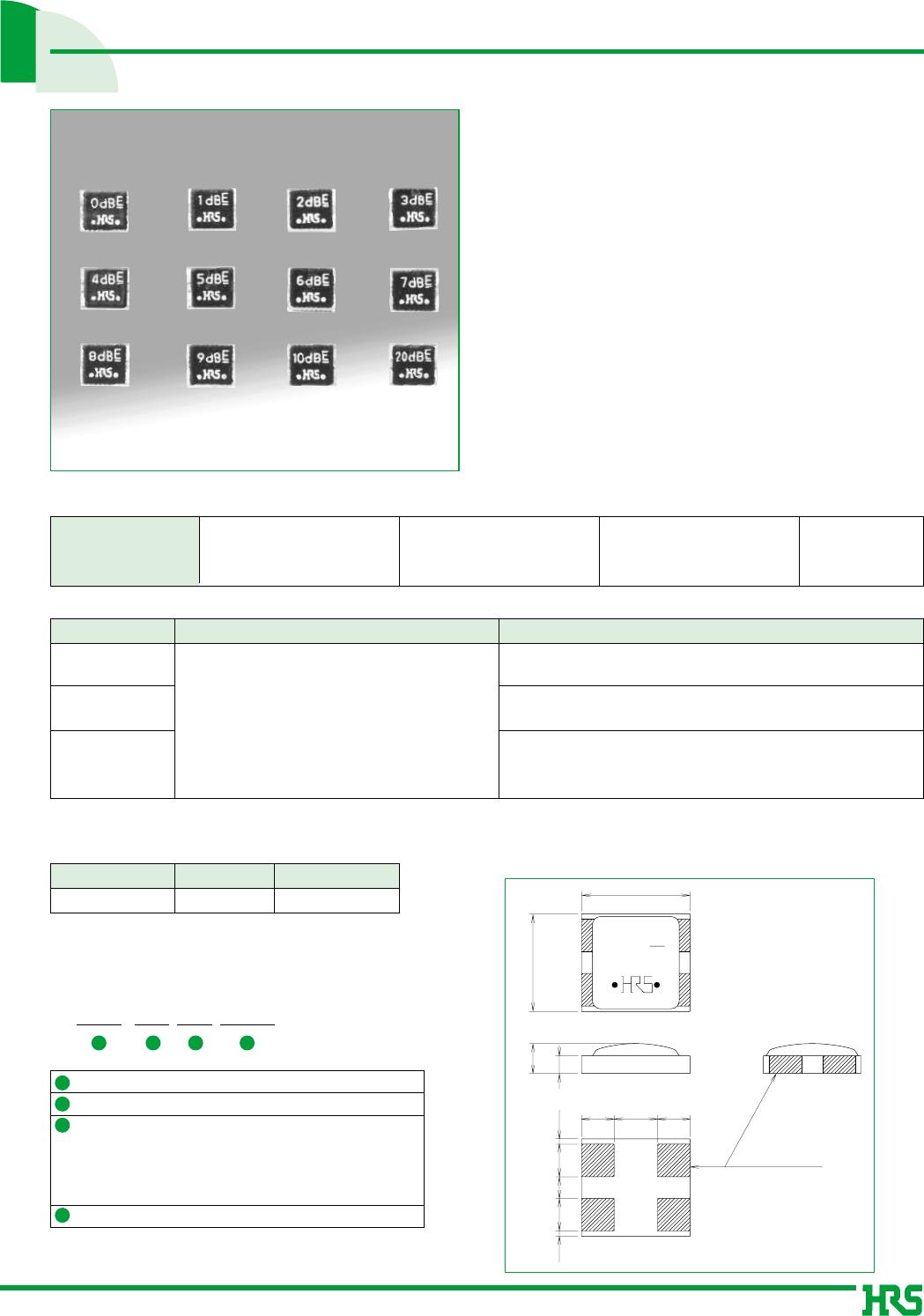
4mm x 3.6 mm x 1.4 mm max height and weighting
only 0.1g.
2. Wide Range of Variations for Each Type
of Attenuator
Attenuation levels available in 1 dB steps from 0 to
10 dB, and 20 dB for a total of 12 types of
variations.
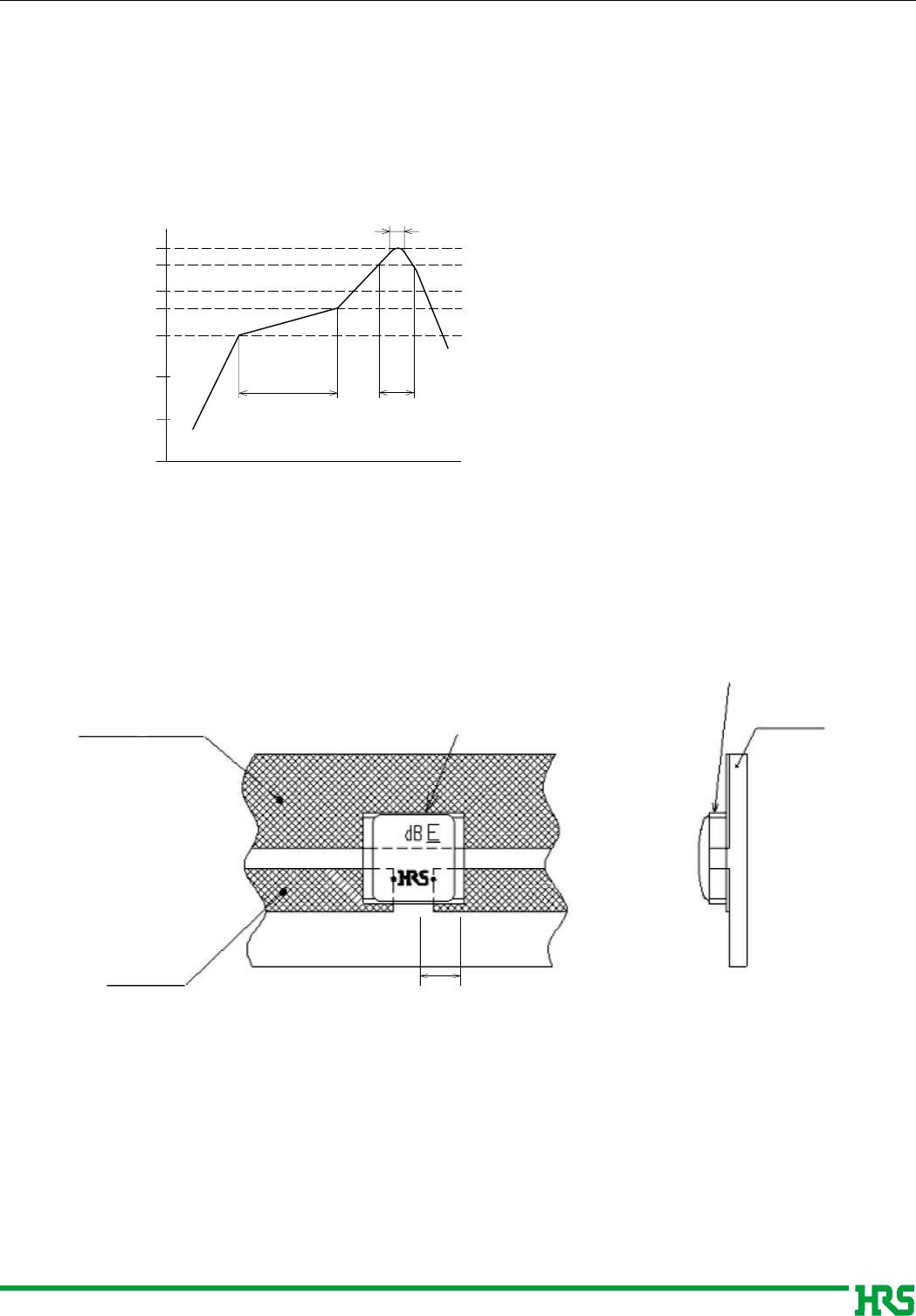
3. Automatic placement
Supplied in embossed packaging to allow
placement with automatic equipment.
Individual piece packaging is also available.
■Product Specifications
Ratings
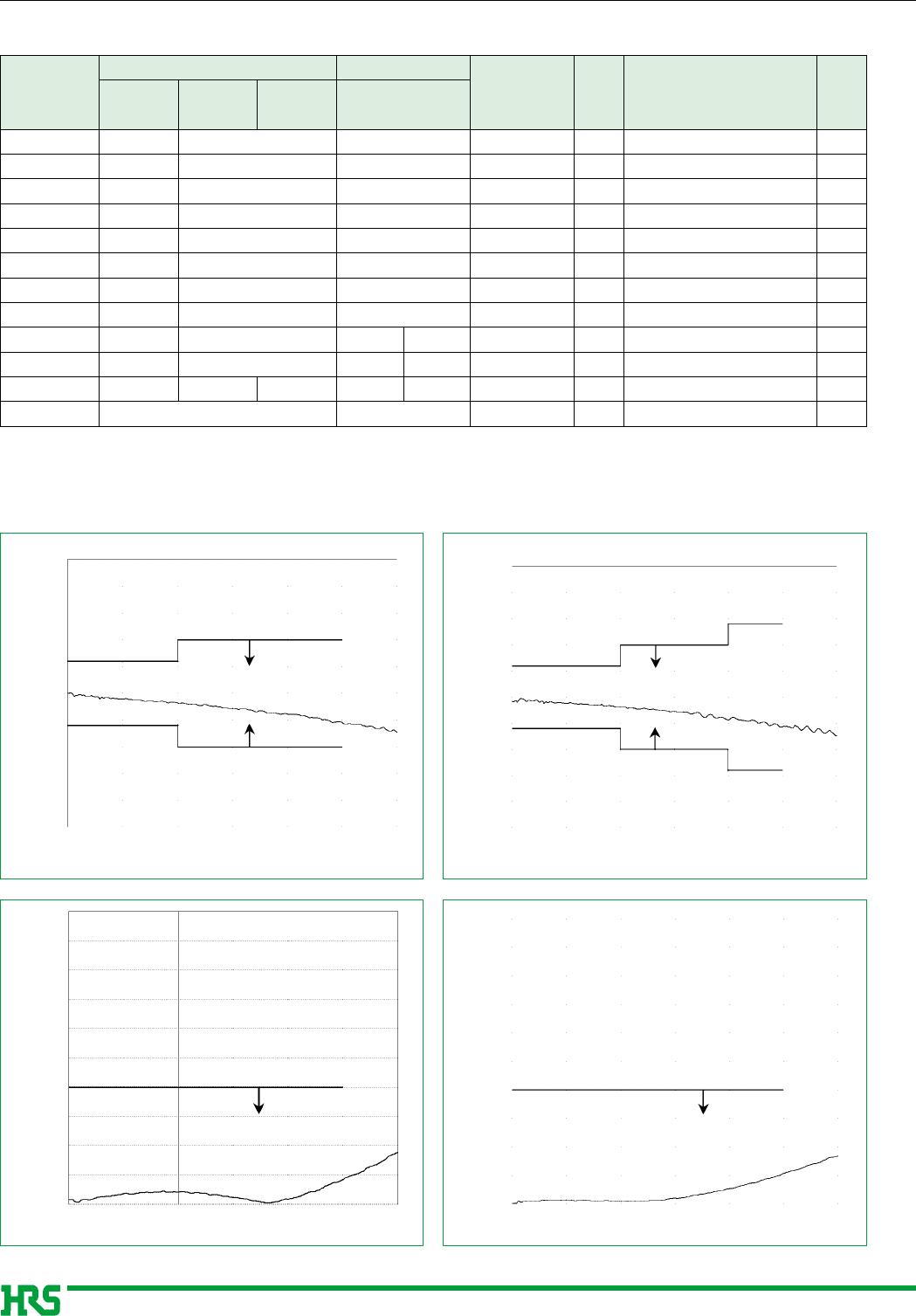
Frequency range
Characteristic impedance
Maximum input power
DC to 2.5GHz (Note)
50ø
1W
Operating temperature
Operating humidity
-10ç to +65ç
95% max.
Item
1.Vibration
2.Shock
3.
Temperature cycle
Characteristic requirement Conditions
No electrical discontinuity of 1µs or more.
No damage, cracks, or parts dislocation.
Frequency of 10 to 2000 Hz, overall amplitude of 1.5mm,
acceleration of 98m/s
2
, 2 hours in each of the 3 directions.
Acceleration of 490m/s
2
, sine half-wave waveform, 3 cycles in
each of the 3 axis.
Temperature : -55ç / +15ç to +35ç / +85ç / +15ç to +35ç
Time : 30
/
2 to 3
/
30
/
2 to 3 (Minutes)
5 cycles
Note: DC to 600MHz for AT-2220.
Component
Attenuation element
Material Finish
Metal film Tin-lead plated
The test method conforms to MIL-STD-202.
■Materials
AX:Fixed attenuator
Series name :2200 Series
Attenuation
00-(0) : 0 dB (Through)
01 : 1dB
06 : 6dB
(40): RoHS Compliant
1
2
3
4
■Ordering information
■Dimensions
AT-2203 shown
SMT Stripline Mounting Fixed Attenuators
AT-2200 Series
The product information in this catalog is for reference only. Please request the Engineering Drawing for the most current and accurate design information.
All non-RoHS products have been discontinued, or will be discontinued soon. Please check the products status on the Hirose website RoHS search at www.hirose-connectors.com, or contact your Hirose sales representative.