Optical and Mechanical
Encoders
Grayhill, Inc. • 561 Hillgrove Avenue • LaGrange, Illinois 60525-5997 • USA • Phone: 708-354-1040 • Fax: 708-354-2820 • www.grayhill.com
Optical Encoders
Available from your local Grayhill Distributor. For prices and discounts, contact a local Sales Office, an authorized local Distributor or Grayhill.
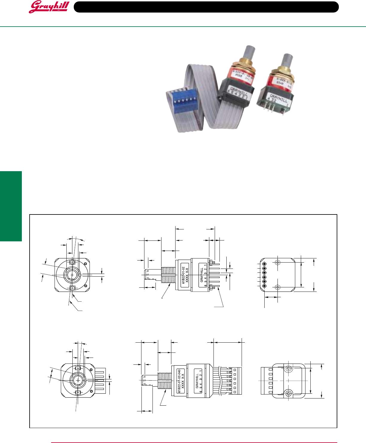
Custom shaft and bushing lengths, shaft/panel seal, and additional supply voltages are available through Grayhill only.
Control knobs available, see page I-57.
Materials and Finishes
Detent Cover: Thermosetting plastic
Bushing: Zinc casting, cadmium-plated per
QQP–416, Class 2, Type II
Shaft: Reinforced thermoplastic
Note: Earlier
versions may have electropolished stainless
steel shafts (still available in customs only).
Detent Balls: Passivated, stainless steel
Detent Spring: Tinned music wire
Printed Circuit Boards: NEMA Grade FR-4
Board Terminals: Copper alloy, CDA No. 725
Through Bolts: Stainless steel, unplated
Through Bolt Nuts: Stainless steel
Switch Assembly Cover and Code Rotor:
PBT polyester thermoplastic
Mounting Hardware: One brass, cadmium-
plated nut and lockwasher supplied with each
switch. Nut is 0.094" thick by 0.562" across flats.
Strain Relief: PBT polyester thermoplastic
(cable version only)
Cable: 26 AWG, stranded/tinned wire, PVC
coated on .100 (2,54) centers (cable version
only)
Operating Torque: 2.0 ± .75 in-oz
Rotational Life: more than 1,000,000 cycles
of operation (1 cycle = 360° rotation and
return)
Shaft Push Out Force: 50 lbs minimum
Mounting Torque: 15 in-lbs maximum
Environmental Ratings
Operating Temperature Range: -40°C to 85°C
Storage Temperature Range: -55°C to 100°C
Vibration Resistance: Harmonic motion with
amplitude of 15g, within a varied 10 to 2000
Hz frequency for 12 hours per MIL-STD-202,
Method 204
Shock Resistance: Test 1: 100g for 6 mS half
sine wave with velocity change of 12.3 ft/s.
Test 2: 100g for 6 mS, sawtooth wave with
velocity change of 9.7 ft/s.
Relative Humidity: 90–95% at 40°C for 96
hours
ACCESSORIES
See page I-41.
SPECIFICATIONS
Pushbutton Switch Ratings
Rating: 5 Vdc, 10 mA, Resistive
Contact Resistance: less than 10 (TTL or
CMOS Compatible)
Voltage Breakdown: 250 Vac between
mutually insulated parts.
Contact Bounce: Less than 4 milliseconds at
make and less than 10 milliseconds at break
Actuation Life: 3,000,000 operations
Actuation Force: Maximum actuation force
of 615 grams and a minimum actuation force
of 415 grams.
Encoder Ratings
Coding: 2-bit quadrature coded output
Operating Voltage: 5 ±.25 Vdc
Supply Current: 30 mA maximum at 5 Vdc
Logic High: 3.8V minimum
Logic Low: 0.8V maximum
Logic Rise and Fall Times: Rise Time less
than 30 mS at 16.6 RPM. Fall Time less tham
30 mS at 16.6 RPM.
1
2
3
4
5
6
POWER +5V
OUTPUT A
OUTPUT B
N.O.
PUSHBUTTON
SWITCH
GROUND
PIN#
R*
R*
150Ω
*EXTERNAL PULL UP RESISTORS REQUIRED FOR OPERATION. 8.2 kΩ
IS SUGGESTED FOR TTL; 3.3 kΩ IS SUGGESTED FOR CMOS
•
Clockwise Rotation
Position Output A Output B
1
2
3
4
•
••
•
Indicates logic high; blank indicates logic
low. Code repeats every 4 positions.
CIRCUITRY, TRUTH TABLE, AND WAVEFORM: Standard Quadrature 2-Bit Code
OUTPUT
A
OUTPUT
B
HIGH
LOW
HIGH
LOW
POSITION NUMBER
1 2 3 4 5 6
ORDERING INFORMATION
Series
Style: B = Standard, unsealed
Angle of Throw: 11 = 11.25° or 32 Positions
15 = 15° or 24 Positions
22 = 22.25° or 16 Positions
Coding: 01 = Quadrature
Pushbutton Option: 01 = Without pushbutton, 02 = With pushbutton
61B11–01–02–020
Termination: Blank (no dash or numbers) = pins as described in drawing
Cable Termination 020 = 2.0 inches minimum to 250 = 25 inches maximum. Provided in increments
of 1/2 inch. Example 035 = 3.5", 060 = 6 inches. Cable is terminated with standard Amp Connector
640442-6. Use any 6 position, .100 center header to mate with the cable assembly. Contact Grayhill
I-20