AOTF10N60L_002

AOT10N60/AOB10N60/AOTF10N60
TYPICAL ELECTRICAL AND THERMAL CHARACTERISTICS
0
3
6
9
12
15
0 10 20 30 40 50
Q
g
(nC)
Figure 7: Gate-Charge Characteristics
V
GS
(Volts)
V
DS
=480V
I
D
=10A
1
10
100
1000
10000
0.1 1 10 100
V
DS
(Volts)
Figure 8: Capacitance Characteristics
Capacitance (pF)
C
iss
C
oss
C
rss
0.01
0.1
1
10
100
1 10 100 1000
V
DS
(Volts)
I
D
(Amps)
Figure 9: Maximum Forward Biased Safe Operating
Area for AOT10N60/AOB10N60 (Note F)
10
µ
s
10ms
1ms
DC
R
DS(ON)
limited
T
J(Max)
=150°C
T
C
=25°C
100
µ
s
0.01
0.1
1
10
100
1 10 100 1000
V
DS
(Volts)
I
D
(Amps)
Figure 10: Maximum Forward Biased Safe Operating
Area for AOTF10N60 (Note F)
10
µ
s
10ms
1ms
0.1s
DC
R
DS(ON)
limited
T
J(Max)
=150°C
T
C
=25°C
100µs
1s
0
2
4
6
8
10
12
0 25 50 75 100 125 150
T
CASE
C)
Figure 11: Current De-rating (Note B)
Current rating I
D
(A)
Rev7: Jul 2011 www.aosmd.com Page 4 of 6
AOT10N60/AOB10N60/AOTF10N60
TYPICAL ELECTRICAL AND THERMAL CHARACTERISTICS
0.001
0.01
0.1
1
10
0.00001 0.0001 0.001 0.01 0.1 1 10 100
Pulse Width (s)
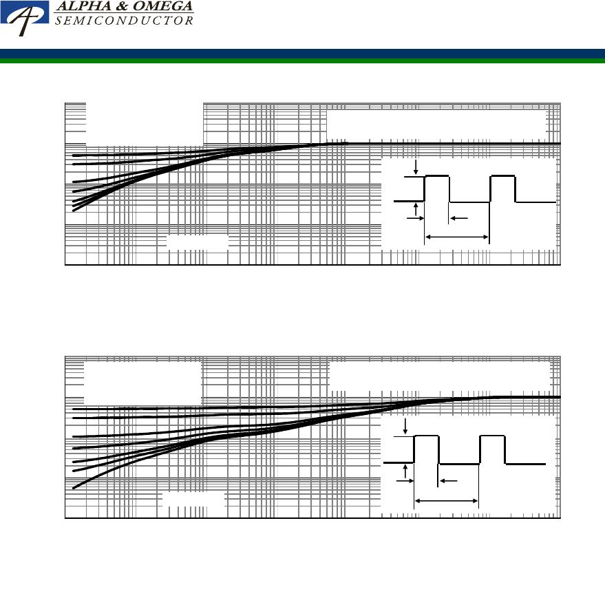
Figure 12: Normalized Maximum Transient Thermal Impedance for AOT10N60/AOB10N60 (Note F)
Z
θ
θ
θ
θ
JC
Normalized Transient
Thermal Resistance
D=T
on
/T
T
J,PK
=T
C
+P
DM
.Z
θJC
.R
θJC
R
θJC
=0.5°C/W
In descending order
D=0.5, 0.3, 0.1, 0.05, 0.02, 0.01, single pulse
T
on
T
P
D
Single Pulse
0.001
0.01
0.1
1
10
0.00001 0.0001 0.001 0.01 0.1 1 10 100
Pulse Width (s)
Figure 13: Normalized Maximum Transient Thermal Impedance for AOTF10N60 (Note F)
Z
θ
θ
θ
θ
JC
Normalized Transient
Thermal Resistance
D=T
on
/T
T
J,PK
=T
C
+P
DM
.Z
θJC
.R
θJC
R
θJC
=2.5°C/W
In descending order
D=0.5, 0.3, 0.1, 0.05, 0.02, 0.01, single pulse
Single Pulse
T
on
T
P
D
Rev7: Jul 2011 www.aosmd.com Page 5 of 6
AOT10N60/AOB10N60/AOTF10N60
-
+
VDC
Ig
Vds
DUT
-
+
VDC
Vgs
Vgs
10V
Qg
Qgs Qgd
Charge
Gate Charge Test Circuit & Waveform
-
+
VDC
DUT
Vdd
Vgs
Vds
Vgs
RL
Rg
Vgs
Vds
10%
90%
Resistive Switching Test Circuit & Waveforms
t t
r
d(on)
t
on
t
d(off)
t
f
t
off
Vdd
Vgs
Id
Vgs
Rg
DUT
-
+
VDC
L
Vgs
Vds
Id
Vgs
BV
I
Unclamped Inductive Switching (UIS) Test Circuit & Waveforms
Ig
Vgs
-
+
VDC
DUT
L
Vds
Vgs
Vds
Isd
Isd
Diode Recovery Test Circuit & Waveforms
Vds -
Vds +
I
F
AR
DSS
2
E = 1/2 LI
dI/dt
I
RM
rr
Vdd
Vdd
Q = - Idt
t
rr
AR
AR
Rev7: Jul 2011 www.aosmd.com Page 6 of 6

AOTF10N60L_002

Mfr. #:
Manufacturer:
Description:
MOSFET N-CH 600V 10A TO220F
Lifecycle:
New from this manufacturer.
Delivery:
DHL FedEx Ups TNT EMS
Payment:
T/T Paypal Visa MoneyGram Western Union

Products related to this Datasheet