B241
DF14 Series●1.25mm Pitch Super Low profile Crimping Connector
1.
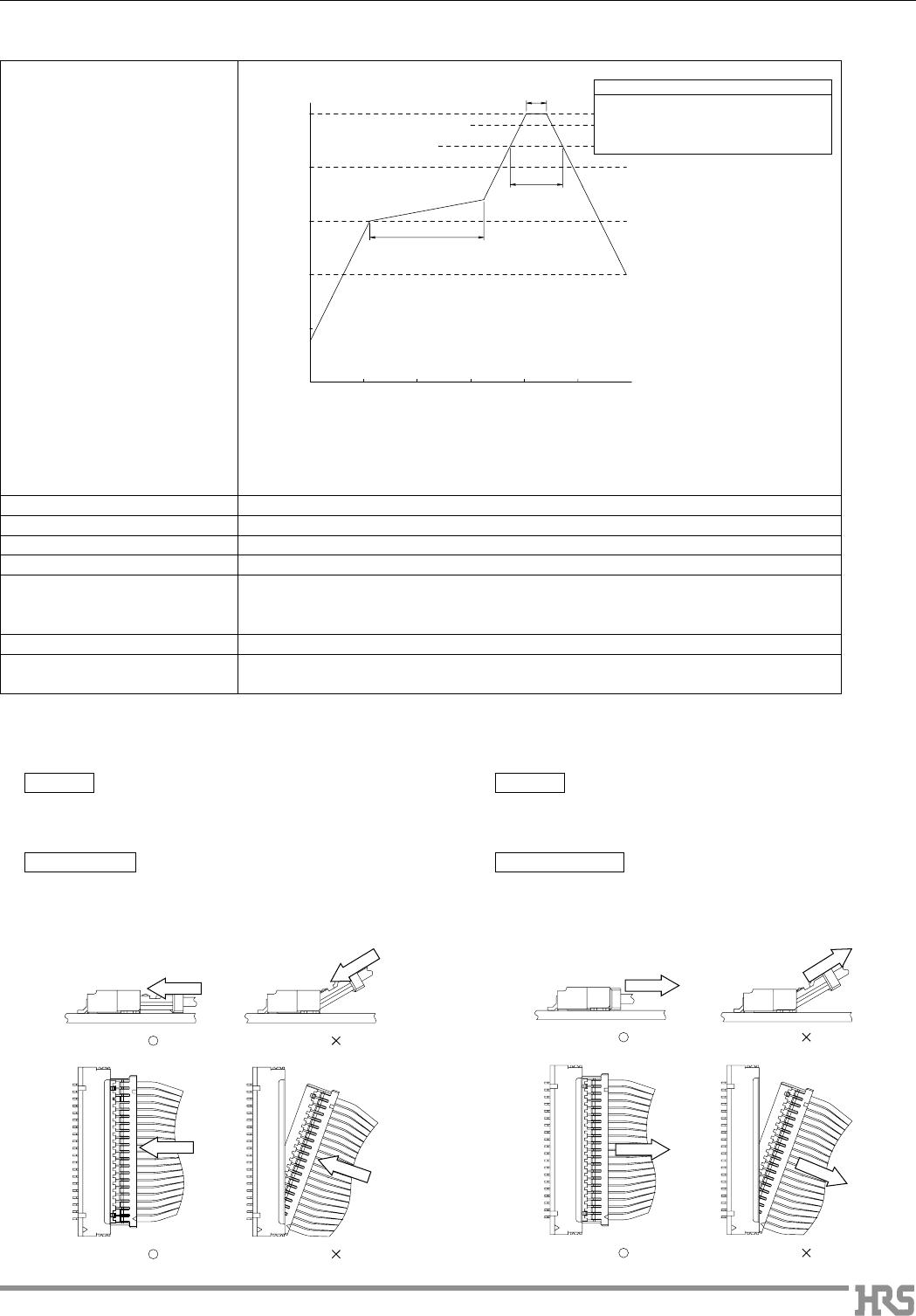
Recommended Temperature Profile (SMT)
Note 1.Up to 2 cycles of Reflow soldering are possible under the same conditions, provided
that there is a return to normal temperature between the first and second cycle.
Note 2.The temperature profile indicates the board surface temperature at the point of
contacts with the connector terminals.
2.
Recommended Manual Soldering Condition (SMT)
Manual soldering: 290ç for 2 seconds
3.
Recommended Screen Thickness (SMT)
0.15 to 0.2mm
4. Board Sled (SMT) Max 0.03mm at the connector center area, based on both connector edges
5. Cleaning Condition Refer to Nylon Connector Use Hand book.
6. Connection Condition Refer to Nylon Connector Use Hand book.
■Be careful to carry out the crimping operation according to the "Crimping Condition Sheet"
and "Crimping Quality Reference", because the crimping contact style is too small.
7. Precautions Refer to Nylon Connector Use Hand book.
8. Cautions ■Be careful for an excessive scoop insertion/extraction, which will cause damage to the
product.
BPrecautions
BPrecautions
DiagonalParallel
DiagonalParallel
DiagonalParallel
DiagonalParallel
100ç
150ç
200ç
250ç
Max. 240
220
Time
Temperature
10s max.
60 to 120s
Preheating
60s max.
Soldering
IR reflow condition
Preheating area
150ç for 60 to 120 seconds
Soldering area 250 for 10 seconds max.
220ç min. 60 seconds max.
Precautions at Time of InsertionPrecautions at Time of Disconnection
Handling
Method: Lightly grasping the base of the cable, press the
connector with your finger and insert it.
Handling
Method: Grasp the cable so that the entire cable is pulled
evenly and pull it out.
Insertion Angle
[Caution] Do not insert at an angle of 30° or greater. Doing so
will cause contact deformation or case damage.
Method: Insert with the connector parallel.
Angle of Removal
[Caution] Do not remove at an angle of 30° or greater. Doing so
will cause contact deformation or case damage.
Method: Remove with the connector parallel.
The product information in this catalog is for reference only. Please request the Engineering Drawing for the most current and accurate design information.
All non-RoHS products have been discontinued, or will be discontinued soon. Please check the products status on the Hirose website RoHS search at www.hirose-connectors.com, or contact your Hirose sales representative.
Nov.1.2016 Copyright 2016 HIROSE ELECTRIC CO., LTD. All Rights Reserved.
Powered by TCPDF (www.tcpdf.org)
Apr.1.2017 Copyright 2017 HIROSE ELECTRIC CO., LTD. All Rights Reserved.
Powered by TCPDF (www.tcpdf.org)
