MAX2745
Single-Chip Global Positioning System
Receiver Front-End
_______________________________________________________________________________________ 7
Temperature Sensor
The MAX2745 features an on-chip temperature sensor to
facilitate system temperature compensations in conjunc-
tion with the trimmed capacitor. This circuit generates an
output voltage at TEMPOUT, which is used to approxi-
mate the temperature by the following equation:
T = T
O
+ (V
OUT
- V
OUT,TO
)/SG
where SG is the sensor gain, T
O
is factory-trimmed tem-
perature, which can be any value (normally +27°C), and
V
OUT
is the temperature output voltage at T
O
. The coeffi-
cient SG in the above equation is targeted to be between
6mV/°C and 8mV/°C, depending on the temperature.
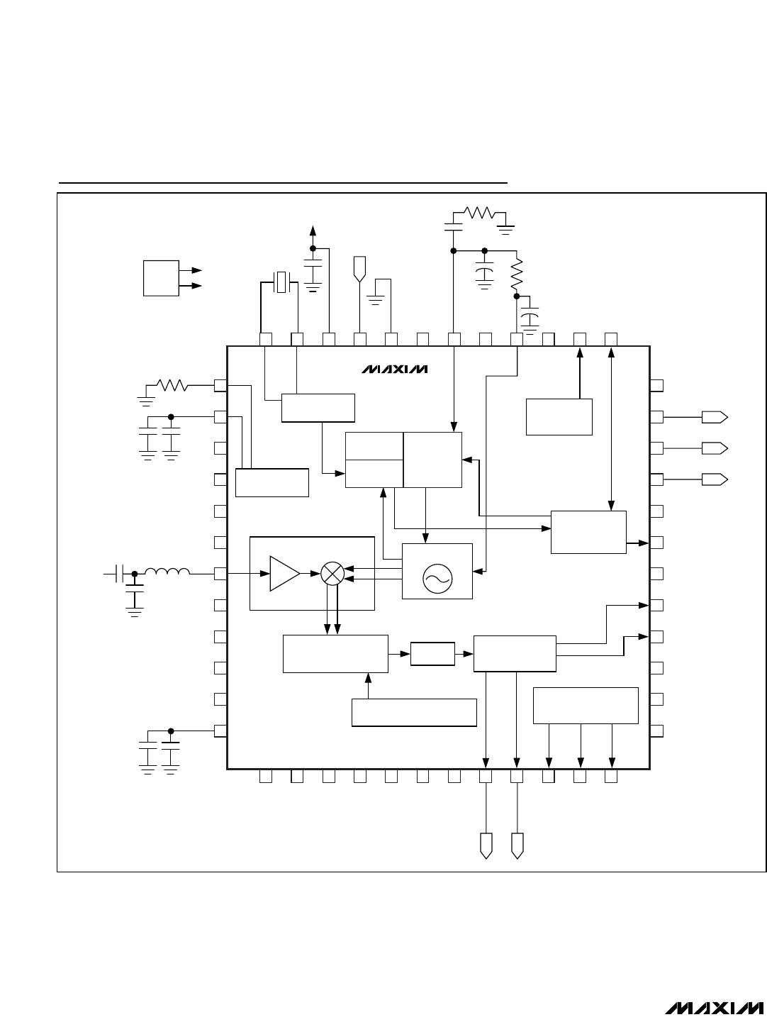
Voltage Booster
The MAX2745 integrates an internal voltage booster to
allow proper operation with supply voltages as low as
1.6V. The circuit includes two 6nF floating external
capacitors connected to VB_CS± (pins 22 and 23) and
a 1µF capacitance to V
OUT
(boosted voltage output,
pin 24). To reduce the output voltage ripple, use an
external LC lowpass filter, which can be built with two
inductors and one capacitor.
Applications Information
Operation with Voltage Booster
Under normal operating conditions, the recommended
power-supply voltage ranges from 2.4V to 3.6V. But
with the integrated voltage booster on-chip, the
MAX2745 can be powered from power-supply voltages
as low as 1.6V, and only requires a minimal number of
external components. This is not the most efficient
operating mode, since the power efficiency will be low-
ered to less than 50%.
As described in the Detailed Description section, to use
the voltage booster, connect 6nF floating capacitors to
VB_CS±, pins 22 and 23, and 1µF bypass capacitor to
V
OUT
, pin 24. Connect V
OUT
(pin 24) to all the power-
supply (V
DD
) pins and pull BST_CTRL, pin 17, high to
activate the booster. Then the MAX2745 can be pow-
ered from supply voltages ranging from 1.6V to 2.3V at
VDD_VB, pin 19, and the voltage booster output can
source up to 25mA current. It is recommended that the
voltage booster be used as a backup supply. To do
this, additional circuits including a voltage monitor and
a switch are needed. These components are inexpen-
sive and can be found in the Maxim product family.
Layout Issues
A properly designed PC board is an essential part of
any RF/microwave circuit. Use the MAX2745 EV kit as a
guide. Use controlled-impedance lines on all frequency
inputs and outputs. Use low inductance connections to
ground on all ground pins and wherever the compo-
nents are connected to ground. Place decoupling
capacitors close to all V
CC
connections. For proper
operation, connect the metal exposed paddle at the
back of the IC to the PC board ground plane with multi-
ple vias.
Chip Information
TRANSISTOR COUNT: 9205
PROCESS: CMOS