SSL2103 All information provided in this document is subject to legal disclaimers. © NXP B.V. 2011. All rights reserved.
Product data sheet Rev. 2.2 — 5 December 2011 10 of 21
NXP Semiconductors
SSL2103
Dimmable Greenchip controller for LED lighting
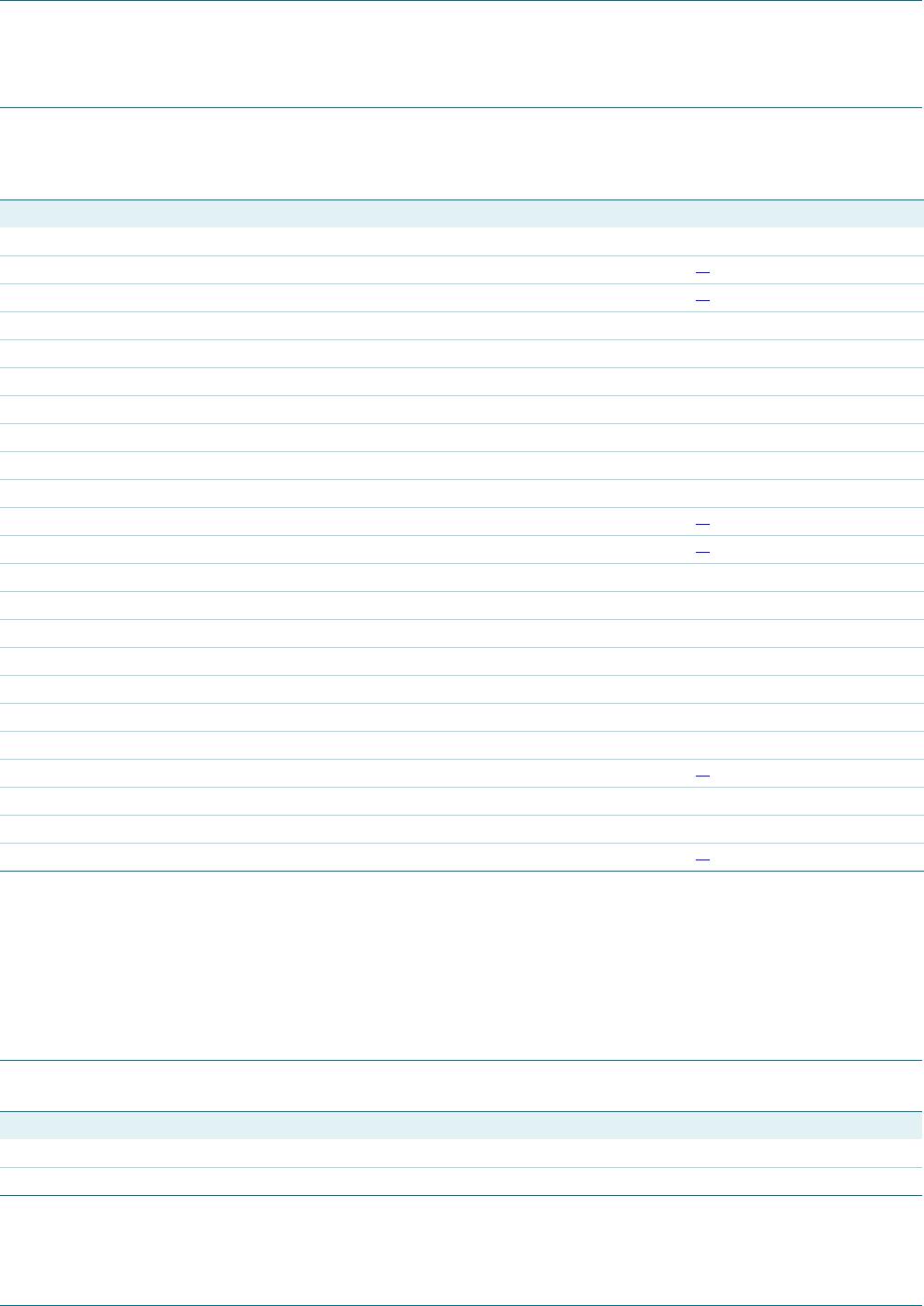
9. Limiting values
[1] Pins V
CC
and RC cannot be current driven.
[2] Pins ISENSE and AUX cannot be voltage driven.
[3] Human body model: equivalent to discharging a 100 pF capacitor through a 1.5 k series resistor.
[4] Charged device model: equivalent to charging the IC up to 1 kV and the subsequent discharging of each pin down to 0 V over a 1
resistor.
10. Thermal characteristics
Table 4. Limiting values
In accordance with the Absolute Maximum Rating System (IEC 60134). All voltages are measured with respect to ground;
positive currents flow into the device.
Symbol Parameter Conditions Min Max Unit
Voltages
V
CC
supply voltage continuous
[1]
0.4 +28 V
V
RC
voltage on pin RC
[1]
0.4 +3 V
V
RC2
voltage on pin RC2 0.4 +3 V
V
BRIGHTNESS
voltage on pin BRIGHTNESS 0.4 +5 V
V
PWMLIMIT
voltage on pin PWMLIMIT 0.4 +5 V
V
SOURCE
voltage on pin SOURCE 0.4 +5 V
V
DRAIN
voltage on pin DRAIN T
amb
=25C 0.4 +600 V
V
HVDET
voltage on pin HVDET T
amb
=25C 0.4 +600 V
Currents
I
ISENSE
current on pin ISENSE
[2]
20 +5 mA
I
AUX
current on pin AUX
[2]
10 +5 mA
I
SB_DRV
current on pin SB_DRV +3.6 mA
I
WB_DRV
current on pin WB_DRV +3.6 mA
General
P
tot
total power dissipation T
amb
=70C - 250 mW
T
stg
storage temperature 55 +150 C
T
amb
ambient temperature 40 +100 C
T
j
junction temperature 40 +150 C
V
ESD
electrostatic discharge voltage human body model;
[3]
Pins 13 and 14 1000 +1000 V
All other pins 2000 +2000 V
charged device model
[4]
500 +500 V
Table 5. Thermal characteristics
Symbol Parameter Conditions Typ Unit
R
th(j-a)
thermal resistance from junction to ambient in free air, on JESD51-3 board 123 K/W
j-top
thermal characterization parameter from junction to top in free air, on JESD51-3 board 7 K/W