General Description
Micron’s FBDIMM devices adhere to the currently proposed industry specifications for
FBDIMMs. The following specifications contain detailed information on FBDIMM de-
sign, interfaces, and theory of operation and are listed here for the system designers’
convenience. Refer to the JEDEC Web site for available specifications.
• FBDIMM Design Specification – pending JEDEC approval
• FBDIMM: Architecture and Protocol – JESD206
• FBDIMM: Advanced Memory Buffer (AMB) – JESD82-20
• Design for Test, Design for Validation (DFx) Specification
• Serial Presence-Detect (SPD) for Fully Buffered DIMM – JEDEC Standard No. 21-C,
page 4.1.2.7-1
This DDR2 SDRAM module is a high-bandwidth, large-capacity channel solution that
has a narrow host interface. FBDIMM devices use DDR2 SDRAM devices isolated from
the channel behind an AMB on the FBDIMM. Memory device capacity remains high,
and total memory capacity scales with DDR2 SDRAM bit density.
As shown in the System Block Diagram, the FBDIMM channel provides a communica-
tion path from a host controller to an array of DDR2 SDRAM devices, with the DDR2
SDRAM devices buffered behind an AMB device. The physical isolation of the DDR2
SDRAM devices from the channel enhances the communication path and significantly
increases the reliability and availability of the memory subsystem.
Advanced Memory Buffer
The AMB isolates the DDR2 SDRAM devices from the channel. This single-chip AMB
component, located in the center of each FBDIMM, acts as a repeater and buffer for all
signals and commands exchanged between the host controller and DDR2 SDRAM devi-
ces, including data input and output. The AMB communicates with the host controller
and adjacent FBDIMMs on a system board using an industry-standard, high-speed, dif-
ferential, 1.5V, point-to-point interface. The AMB also enables buffering of memory traf-
fic to support large memory capacities. Refer to the JEDEC JESD82-20 specification for
further information.
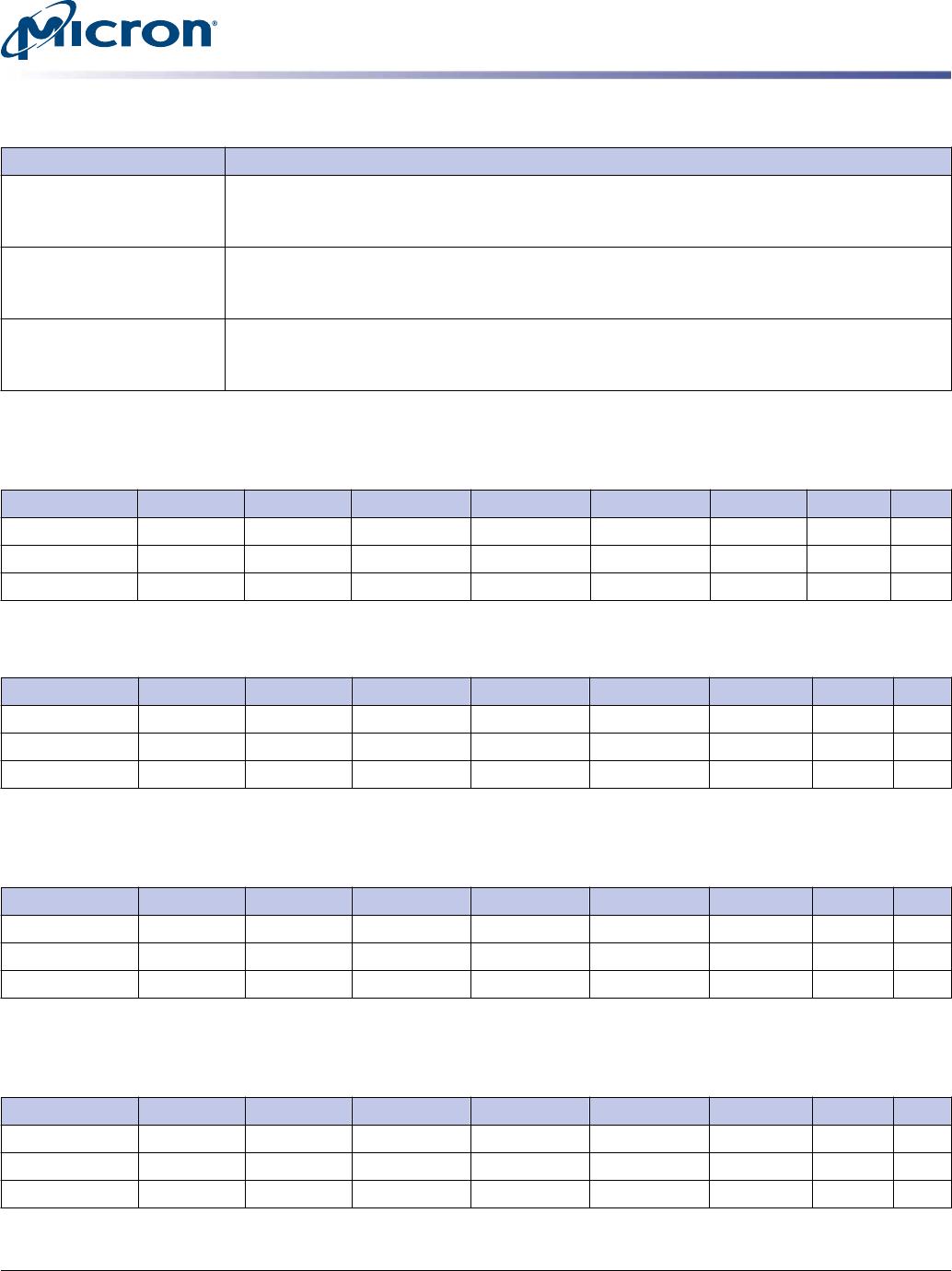
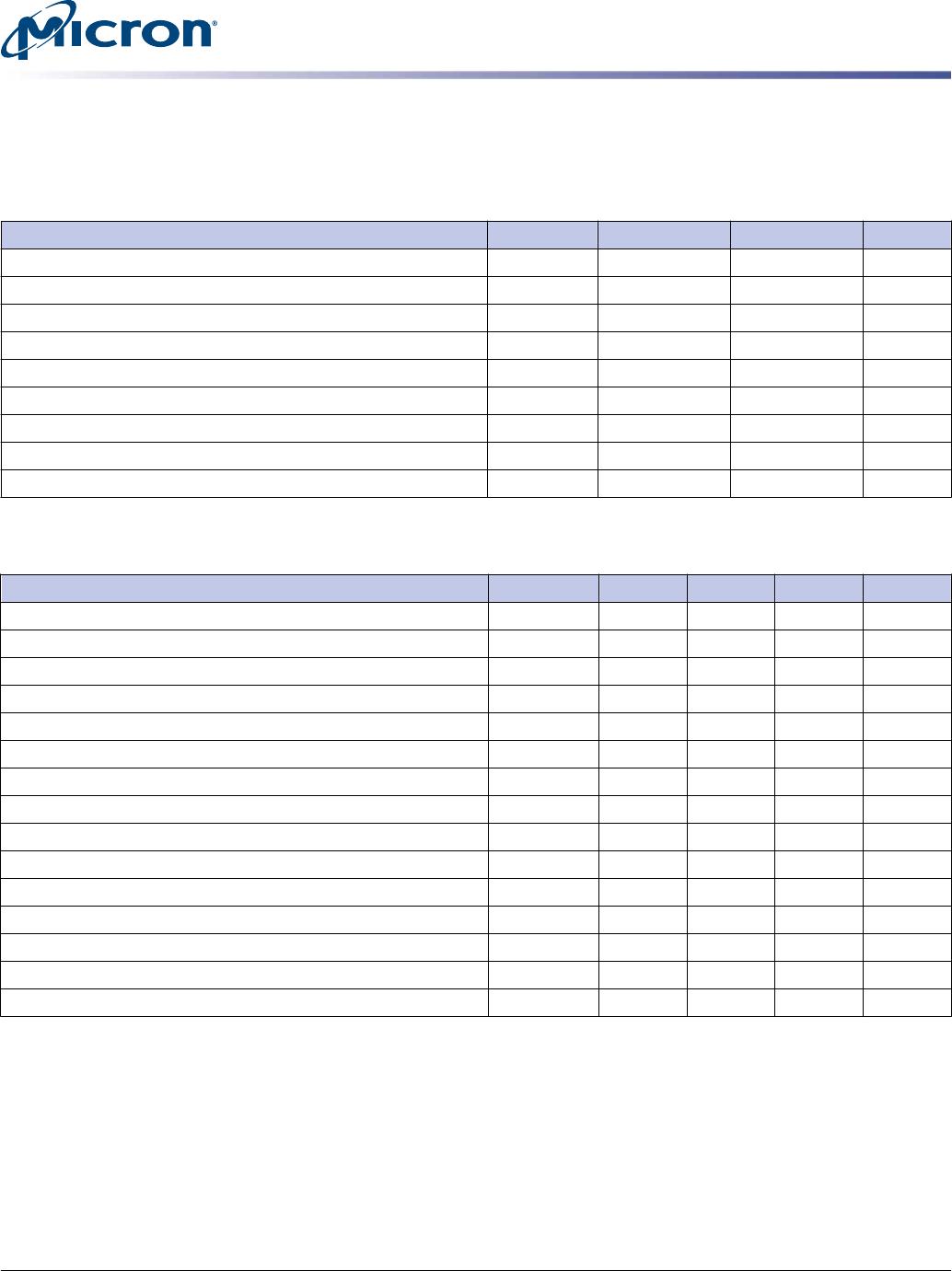
IDD Conditions and Specifications
Table 6: I
DD
Conditions
Symbol Condition
I
DD_IDLE_0
Idle current, single, or last DIMM: L0 state; Idle (0% bandwidth); Primary channel ena-
bled; Secondary channel disabled; CKE HIGH; Command and address lines stable; DDR2
SDRAM clock active
I
DD_IDLE_1
Idle current, first DIMM: L0 state; Idle (0% bandwidth); Primary and secondary channels
enabled; CKE HIGH; Command and address lines stable; DDR2 SDRAM clock active
I
DD_ACTIVE_1
Active power: L0 state; 50% DRAM bandwidth; 67% READ; 33% WRITE; Primary and sec-
ondary channels enabled; DDR2 SDRAM clock active; CKE HIGH
I
DD_ACTIVE_2
Active power, data pass through: L0 state; 50% DRAM bandwidth to downstream DIMM;
67% READ; 33% WRITE; Primary and secondary channels enabled; DDR2 SDRAM clock active;
CKE HIGH; Command and address lines stable
8GB (x72, QR) 240-Pin DDR2 SDRAM FBDIMM
General Description
PDF: 09005aef840ecabe
hts72c1gx72fz.pdf - Rev. B 4/14 EN
7
Micron Technology, Inc. reserves the right to change products or specifications without notice.
© 2010 Micron Technology, Inc. All rights reserved.