Bits 47 to 0: ACC47 to ACC0
These bits report the total power accumulated by each channel. Send the UPDATE command before reading these reg-
isters. The power accumulators do not roll over. If any of the power accumulator overflows, the OVF bit in the CONTROL
command is set and remains set until the UPDATE command is sent.
Bits 15 to 4: V11 to V0
These bits report the last measured common-mode voltage for each channel. The LSB bit weighting is 3.9mV (16V full
scale/4096). The UPDATE command must be sent before reading the channel voltages. The host should wait 500µs after
sending the UPDATE command before reading the VOLTAGE commands.
Bits 7 to 3: ID4 to ID0
These bits report the device identification (ID). The ID is fixed at 05h.
Bits 2 to 0: REV2 to REV0
These bits report the device revision. The device revision is factory set.
Applications Information
Average Power Calculation Example
The average power can be derived in an external calculation as shown below if the current sense resistor value is known.
Power accumulator (48 bit) = 0001CEFBD314h (7767577364 decimal)
Accumulator counter (24 bit) = 0005DEh (1502 decimal)
Current-sense resistor = 10mΩ
Step 1
Calculate the unscaled average power by dividing the power accumulator value with the accumulator count value:
0001CEFBD314h/0005DEh = 4EE921h (5171489 decimal)
Step 2
Calculate the ratio of the Step 1 result to the calculated power full-scale value which is a 28-bit value:
5171489/2
28
= 0.019265
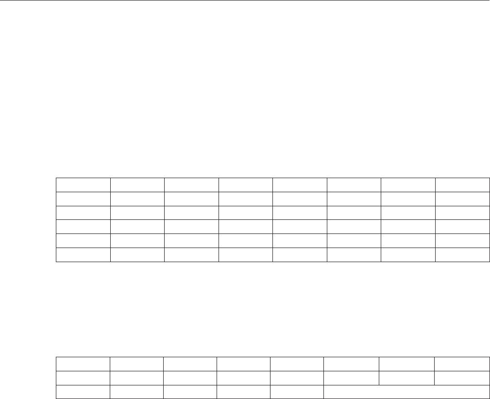
Table 10. Voltage for Channel 1 (07h)—Block Read
Voltage for Channel 2 (08h)—Block Read
Voltage for Channel 3 (09h)—Block Read
Voltage for Channel 4 (0Ah)—Block Read
Table 11. Device ID & Revision Register (0Fh)—Read Byte
BIT 15 BIT 14 BIT 13 BIT 12 BIT 11 BIT 10 BIT 9 BIT 8
NAME: V11 V10 V9 V8 V7 V6 V5 V4
POR: 0 0 0 0 0 0 0 0
BIT 7 BIT 6 BIT 5 BIT 4 BIT 3 BIT 2 BIT 1 BIT 0
NAME: V3 V2 V1 V0 N/A N/A N/A N/A
POR: 0 0 0 0 0 0 0 0
BIT 7 BIT 6 BIT 5 BIT 4 BIT 3 BIT 2 BIT 1 BIT 0
NAME:
ID4 ID3 ID2 ID1 ID0 REV2 REV1 REV0
POR:
0 0 1 0 1 Factory set
Note: Bit positions marked as N/A are not assigned and have no meaning. These bits can be either 0 or 1 when read.
MAX34407 SMBus 4-Channel Wide Dynamic Range
Power Accumulator
www.maximintegrated.com
Maxim Integrated
│
14