– 2 –
by
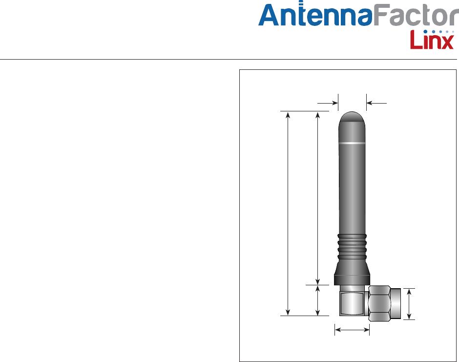
Data Sheet ANT-868-CW-RCS-xxx
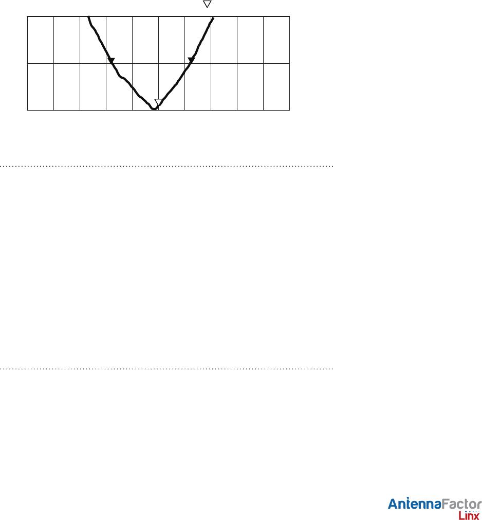
VSWR Graph
What is VSWR?
The Voltage Standing Wave Ratio (VSWR) is a measurement of how well
an antenna is matched to a source impedance, typically 50-ohms. It is
calculated by measuring the voltage wave that is headed toward the load
versus the voltage wave that is reflected back from the load. A perfect
match will have a VSWR of 1:1. The higher the first number, the worse the
match, and the more inefficient the system. Since a perfect match cannot
ever be obtained, some benchmark for performance needs to be set. In
the case of antenna VSWR, this is usually 2:1. At this point, 88.9% of the
energy sent to the antenna by the transmitter is radiated into free space
and 11.1% is either reflected back into the source or lost as heat on
the structure of the antenna. In the other direction, 88.9% of the energy
recovered by the antenna is transferred into the receiver. As a side note,
since the “:1” is always implied, many data sheets will remove it and just
display the first number.
How to Read a VSWR Graph
VSWR is usually displayed graphically versus frequency. The lowest point
on the graph is the antenna’s operational center frequency. In most cases,
this will be different than the designed center frequency due to fabrication
tolerances. The VSWR at that point denotes how close to 50-ohms the
antenna gets. Linx specifies the recommended bandwidth as the range
where the typical antenna VSWR is less than 2:1.
Counterpoise
Quarter-wave or monopole antennas require an associated ground plane
counterpoise for proper operation. The size and location of the ground
plane relative to the antenna will affect the overall performance of the
antenna in the final design. When used in conjunction with a ground
plane smaller than that used to tune the antenna, the center frequency
typically will shift higher in frequency and the bandwidth will decrease.
The proximity of other circuit elements and packaging near the antenna
will also affect the final performance. For further discussion and guidance
on the importance of the ground plane counterpoise, please refer to Linx
Application Note AN-00501: Understanding Antenna Specifications and
Operation.
VSWR Reflected Power
3:1
2:1
1:1
25%
11%
0%
868MHz 968MHz768MHz
1.0899