High Stability Thin Film Flat Chip Resistors
www.vishay.com For technical questions, contact: thinfilmchip@vishay.com
Document Number: 28758
336 Revision: 27-Jun-12
TNPW e3
Vishay
THIS DOCUMENT IS SUBJECT TO CHANGE WITHOUT NOTICE. THE PRODUCTS DESCRIBED HEREIN AND THIS DOCUMENT
ARE SUBJECT TO SPECIFIC DISCLAIMERS, SET FORTH AT www.vishay.com/doc?91000
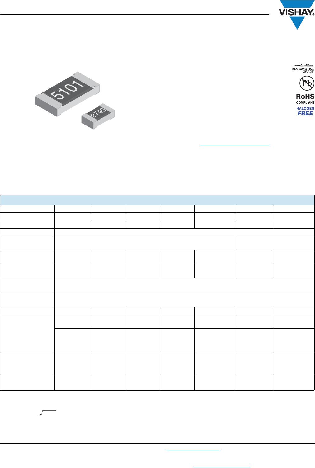
TNPW e3 precision thin film flat chip resistors are the perfect
choice for most fields of modern electronics where highest
reliability and stability is of major concern. Typical
applications include test and measuring equipment, medical
equipment, industrial, and automotive.
FEATURES
• Low temperature coefficient and tight
tolerances (± 0.1 %; ± 10 ppm/K)
• Superior moisture resistivity 0.25 % (85 °C;
56 days; 85 % RH)
• Excellent overall stability at different
environmental conditions 0.05 % (1000 h
rated power at 70 °C)
• AEC-Q200 qualified (sizes 0402 to 1206)
• Waste gas resistant
• Material categorization: For definitions of compliance
please see www.vishay.com/doc?99912
APPLICATIONS
• Test and measuring equipment
• Medical equipment
• Industrial equipment
• Automotive
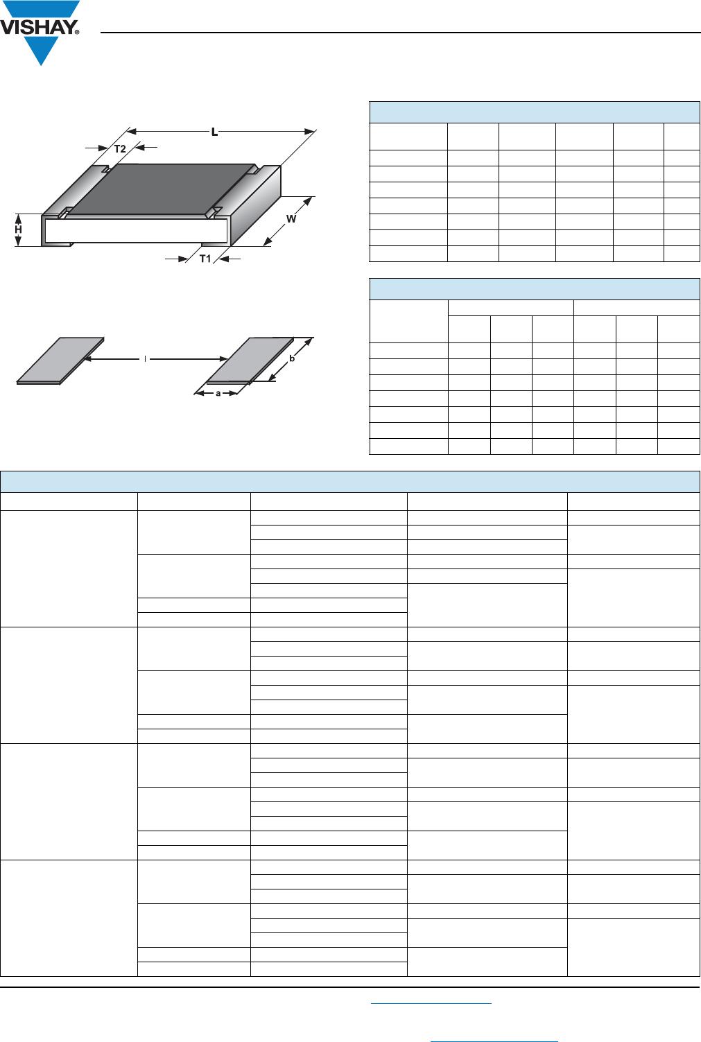
Notes
• TNPW 0402 without marking.
(1)
Size not specified in EN 140401-801.
(2)
Rated voltage . The power dissipation on the resistor generates a temperature rise against the local ambient, depending on the heat
flow support of the printed-circuit board (thermal resistance). Using advanced temperature level may require special considerations towards
the choice of circuit board and solder material. The rated dissipation applies only if the permitted film temperature is not exceeded.
(3)
Measuring conditions in accordance with EN 140401-801.
STANDARD ELECTRICAL SPECIFICATIONS
DESCRIPTION TNPW0402 e3 TNPW0603 e3 TNPW0805 e3 TNPW1206 e3 TNPW1210 e3
(1)
TNPW2010 e3 TNPW2512 e3
(1)
Metric size RR 1005M RR 1608M RR 2012M RR 3216M RR 3225M RR 5025M RR 6332M
Resistance range 10
to 100 k
10
to 332 k
10
to 1 M
10
to 2 M
10
to 3.01 M
10
to 4.99 M
10
to 8.87 M
Resistance tolerance ± 1 %; ± 0.5 %; ± 0.1 %
Temperature
coefficent
± 50 ppm/K; ± 25 ppm/K; ± 15 ppm/K; ± 10 ppm/K ± 50 ppm/K; ± 25 ppm/K
Rated dissipation,
P
70
(2)
0.063 W 0.1 W 0.125 W 0.25 W 0.33 W 0.4 W 0.5 W
Operating voltage,
U
max.
AC/DC
50 V 75 V 150 V 200 V 200 V 300 V 300 V
Permissible film
temperature,
F
max.
155 °C
Operating
temperature range
- 55 °C to 125 °C (155 °C)
Thermal resistance
(3)
870 K/W 550 K/W 440 K/W 220 K/W 170 K/W 140 K/W 110 K/W
Max. resistance
change at
P
70
;
R
/
R
:
10
to 100 k
10
to 332 k
10
to 1 M
10
to 2 M
10
to 3.01 M
10
to 4.99 M
10
to 8.87 M
1000 h
0.05 %
0.05 %
0.05 %
0.05 %
0.05 %
0.05 %
0.05 %
8000 h
0.10 %
0.10 %
0.10 %
0.10 %
0.10 %
0.10 %
0.10 %
225 000 h
0.30 %
0.30 %
0.30 %
0.30 %
0.30 %
0.30 %
0.30 %
Insulation voltage:
U
ins
1 min 75 V 100 V 200 V 300 V 300 V 300 V 300 V
Continuous 75 V 75 V 75 V 75 V 75 V 75 V 75 V
Failure rate:
FIT
observed
0.1 x 10
-9
/h
0.1 x 10
-9
/h
0.1 x 10
-9
/h
0.1 x 10
-9
/h
0.1 x 10
-9
/h
0.1 x 10
-9
/h
0.1 x 10
-9
/h