www.vishay.com For technical questions, contact: thinfilmchip@vishay.com
Document Number: 28758
342 Revision: 27-Jun-12
TNPW e3
Vishay
High Stability Thin Film Flat Chip Resistors
THIS DOCUMENT IS SUBJECT TO CHANGE WITHOUT NOTICE. THE PRODUCTS DESCRIBED HEREIN AND THIS DOCUMENT
ARE SUBJECT TO SPECIFIC DISCLAIMERS, SET FORTH AT www.vishay.com/doc?91000
TEST AND REQUIREMENTS
All tests are carried out in accordance with the following
specifications:
IEC 60115-1, generic specification (includes tests)
EN 140400, sectional specification (includes schedule for
qualification approval)
EN 140401-801, detail specification (includes schedule for
conformance inspection)
The testing also covers most of the requirements specified
by EIA/IS-703 and JIS-C-5202. The tests are carried out
under standard atmospheric conditions in accordance with
IEC 60068-1, 5.3. Climatic category LCT/UCT/56 (rated
temperature range: Lower category temperature, upper
category temperature; damp heat, long term, 56 days) is
valid. Unless otherwise specified the following values apply:
Temperature: 15 °C to 35 °C
Relative humidity: 45 % to 75 %
Air pressure: 86 kPa to 106 kPa (860 mbar to 1060 mbar).
The components are mounted for testing on boards in
accordance with EN 60115-1, 4.31 unless otherwise
specified. The parameters stated in the Test Procedures and
Requirements table are based on the required tests and
permitted limits of EN 140401-801.
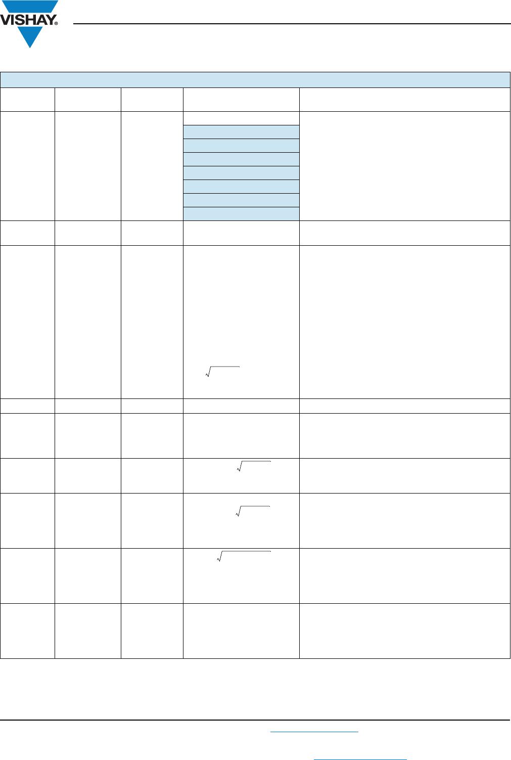
10 000 V
1000 V
100 V
10 V
10 µs
Pulse Duration
t
i
Permissible pulse voltage
U
i, max.
100 µs 1 ms 10 ms 100 ms 1 s 10 s
TNPW1206 e3
TNPW0805 e3
TNPW0603 e3
Conditions:
P
i
≤
P
i, max.
Maximum pulse voltage
U
i, max.
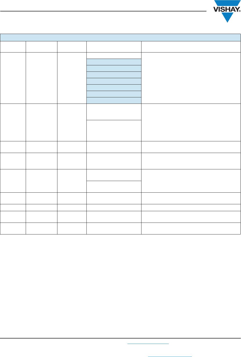
TEST PROCEDURES AND REQUIREMENTS
EN 60115-1
CLAUSE
IEC 60068-2
TEST METHOD
TEST PROCEDURE
REQUIREMENTS
PERMISSIBLE CHANGE
Stability for product types:
TNPW0402 e3
TNPW0603 e3
TNPW0805 e3
TNPW1206 e3
TNPW1210 e3
TNPW2010 e3
TNPW2512 e3
4.5 - Resistance ± 1 %; ± 0.5 %; ± 0.1 %
4.8.4.2 -
Temperature
coefficient
At (20/- 55/20) C and
(20/125/20) °C
± 50 ppm/K; ± 25 ppm/K; ± 15 ppm/K; ± 10 ppm/K
4.25.1 -
Endurance at
70 C
U = or
U = U
max.
;
whichever is the less severe;
1.5 h on; 0.5 h off;
70 °C; 1000 h ± (0.05 % R +0.01)
70 C; 8000 h ± (0.1 % R +0.02)
4.25.3 -
Endurance at
upper category
temperature
125 °C; 1000 h
155 °C; 1000 h
± (0.05 % R + 0.01 )
± (0.1 % R + 0.02 )