AD976/AD976A
–10–
REV. C
OFFSET AND GAIN ADJUSTMENT
The AD976/AD976A is factory trimmed to minimize gain,
offset and linearity errors. In some applications, where the ana-
log input signal is required to meet the full dynamic range of the
ADC, the gain and offset errors need to be externally trimmed
to zero. Figure 7 shows the required trim circuitry to correct for
these offset and gain errors. Figure 8 shows the bipolar transfer
characteristic of the AD976/AD976A.
Where adjustment is required, offset error must be corrected
before gain error. To achieve this, trim the offset resistor R3
while the input voltage is 1/2 LSB below ground. By applying
a voltage of –152.6 µV at the input and adjusting the potentiom-
eter until the major carry transition is located between 1111
1111 1111 1111 and 0000 0000 0000 0000, the internal offset
can be corrected. To adjust the gain error, an analog signal
should be input at either the first code transition (ADC negative
full-scale) or the last code transition (ADC positive full-scale).
Thus, to adjust for full-scale error, an input voltage of 9.999542 V
(FS/2–3/2 LSBs) can be applied to the input and R4 should be
adjusted until the output code flickers between the last positive
code transition 0111 1111 1111 1111 and 0111 1111 1111 1110.
Should the first code transition need adjusting, the trim procedure
should consist of applying an analog input signal of –9.999847 V
(–FS/2 + 1/2 LSB) to the input and adjusting the trim until
the output code flickers between 1000 0000 0000 0000 and
1000 0000 0000 0001.
The external 200 and 33.2K resistor shown in the data sheet for
the AD976 provide compensation for an internal adjustment of the
offset and gain which allows calibration with a single supply. These
resistors may not be required in some applications but it should be
noted that their removal will result in offset and gain errors in
addition to those listed in the electrical specifications of the data
sheet. Tables I and II illustrate the worst case range for Bipolar
Zero (offset) error and Full-Scale (gain) error for the AD976 and
the AD976A. All error terms are with respect to the A/D (i.e., a
negative offset in the table would have to be corrected with an
externally applied positive voltage).
R5
576kV
+5V
R4
50kV
V
IN
AGND1
REF
CAP
AGND2
610V
INPUT
R2
33.2kV
C2
2.2mF
AD976/
AD976A
R1
200V
C1
2.2mF
R3
50kV
Figure 7. Input Connection with Offset and Gain Adjustment
OUTPUT
CODE
011...111
011...110
000...001
000...000
111...111
100...010
100...001
100...000
0V
(V
REF
/2) – 1 LSB
(V
REF
/2) + 1 LSB
+ FS – 1 LSB
FS = V
REF
V
1LSB =
FS
65536
V
REF
/2
V
IN
=
(
AIN(+) - AIN(-)
)
– INPUT VOLTAGE
Figure 8. The Bipolar Transfer Characteristic of the
AD976/AD976A
Table I. Offset and Gain Error for AD976
With Both External Without the External With the External 33.2K Without Either External
Error Term Resistors Included 33.2K Resistor Resistor Grounded Resistors Included
Offset Error –10 mV < Error < 10 mV –25 mV < Error < –5 mV –25 mV < Error < –5 mV –40 mV < Error < –15 mV
+Full Scale –0.50% < Error < 0.50%
1
–0.05% < Error < 0.95% –0.65% < Error < 0.35% 0.55% < Error < 1.90%
Error –0.25% < Error < 0.25%
2
–Full Scale –0.50% < Error < 0.50%
1
0.25% < Error < 1.25% –0.65% < Error < 0.35% –2.5% < Error < –1.0%
Error –0.25% < Error < 0.25%
2
Table II. Offset and Gain Error for AD976A
With Both External Without the External With the External 33.2K Without Either External
Error Term Resistors Included 33.2K Resistor Resistor Grounded Resistors Included
Offset Error –10 mV < Error < 10 mV –25 mV < Error < –5 mV –25 mV < Error < –5 mV –55 mV < Error < –25 mV
+Full Scale –0.50% < Error < 0.50%
1
–0.05% < Error < 0.95% –0.65% < Error < 0.35% 1.0% < Error < 2.50%
Error –0.25% < Error < 0.25%
2
–Full Scale –0.50% < Error < 0.50%
1
0.25% < Error < 1.25% –0.65% < Error < 0.35% –3.50% < Error < –1.75%
Error –0.25% < Error < 0.25%
2
NOTES
1
For A grade part.
2
For B grade part.
AD976/AD976A
–11–
REV. C
VOLTAGE REFERENCE
The AD976/AD976A has an on-chip temperature compensated
bandgap voltage reference that is factory trimmed to 2.5 V
± 20 mV. The full-scale range of the ADC is equal to ±4V
REF
.
Thus, the nominal range will be ±10 V.
The accuracy of the AD976 over the specified temperature
range is dominated by the drift performance of the voltage refer-
ence. The on-chip voltage reference is laser-trimmed to provide
a typical drift of 7 ppm/°C. This typical drift characteristic is
shown in Figure 13, which is a plot of the change in reference
voltage (in mV) versus the change in temperature—notice the
plot is normalized for zero error at +25°C. If improved drift
performance is required, an external reference such as the
AD780 should be used to provide a drift as low as 3 ppm/°C. In
order to simplify the drive requirements of the voltage reference
(internal or external), an onboard reference buffer is provided.
The output of this buffer is provided at the CAP pin and is
available to the user; however, when externally loading the refer-
ence buffer, it is important to make sure that proper precautions
are taken to minimize any degradation in the ADC’s perfor-
mance. Figure 14 shows the load regulation of the reference
buffer. Notice that this figure is also normalized so that there is
zero error with no dc load. In the linear region, the output im-
pedance at this point is typically 1 ohm. Because of this 1 ohm
output impedance, it is important to minimize any ac or input
dependent loads that will lead to increased distortion. Any dc
loads will simply act as a gain error. Although the typical char-
acteristic of Figure 14 shows that the AD976 is capable of driv-
ing loads greater than 15 mA, it is not recommended that the
steady state current exceed 2 mA.
In addition to the on-chip reference, an external 2.5 V reference
can be applied. When choosing an external reference for a
16-bit application, however, careful attention should be paid to
noise and temperature drift. These critical specifications can
have a significant effect on the ADC performance.
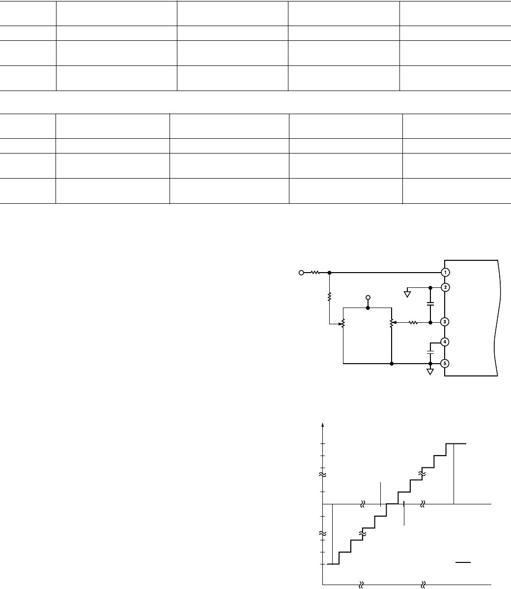
Figure 9 shows the AD976/AD976A with the AD780 voltage
reference applied to the REF pin. The AD780 is a bandgap
reference that exhibits ultralow drift, low initial error, and low
output noise. For low power applications, the REF192 provides
a low quiescent current, high accuracy and low temperature
drift solution.
C4
0.1mF
V
ANA
C3
1mF
V
IN
AGND1
REF
CAP
AGND2
610V INPUT
R2
33.2kV
C2
2.2mF
AD976/
AD976A
R1
200V
C1
2.2mF
AD780
GND
V
OUT
TEMP
V
IN
0.1mF
+5V
Figure 9. AD780 External Reference Connection to the
AD976/AD976A
AC PERFORMANCE
The AD976/AD976A is fully specified and tested for dynamic
performance specifications. The ac parameters are required for
signal processing applications such as speech recognition and
spectrum analysis. These applications require information on
the ADC’s effect on the spectral content of the input signal.
Hence, the parameters for which the AD976/AD976A is
specified include: S/(N+D), THD and Spurious Free Dynamic
Range. These terms are discussed in greater detail in the follow-
ing sections.
As a general rule, it is recommended that the results from sev-
eral conversions be averaged to reduce the effects of noise, thus
improving parameters such as S/(N+D) and THD. The ac per-
formance of the AD976/AD976A can be optimized by operating
the ADC at its maximum sampling rate of 100 kHz/200 kHz
and by digitally filtering the resulting bit stream to the desired
signal bandwidth. By distributing noise over a wider frequency
range, the noise density in the frequency band of interest can be
reduced. For example, if the required input bandwidth is 50 kHz,
the AD976A could be oversampled by a factor of 2. This would
yield a 3 dB improvement in the effective SNR performance.
FREQUENCY – kHz
0
–10
–150
0 10010 20 30 40
–40
–70
–130
–140
–20
–30
–60
–50
dB
–90
–120
–80
–110
–100
50 60 70 80 90 955 1525354555657585
F
SAMPLE
= 200kHz
F
IN
= 45kHz
SNR = 86.23dB
THD = –105.33dB
100%
Figure 10. FFT PLOT
DC PERFORMANCE
The factory calibration scheme used for the AD976/AD976A
compensates for bit weight errors that may exist in the capacitor
array. The mismatch in capacitor values is adjusted (using the
calibration coefficients) during a conversion, resulting in excellent
dc linearity performance. Figures 11, 12, 15, 16, 17 and 18,
respectively, show typical INL, typical DNL, typical positive and
negative INL and DNL distribution plots for the AD976/AD976A
at +25°C.
A histogram test is a statistical method for deriving an A/D
converter’s differential nonlinearity. A ramp input is sampled
by the ADC and a large number of conversions are taken and
stored. Theoretically, the codes would all be the same size and
therefore have an equal number of occurrences. A code with an
average number of occurrences would have a DNL of “0.” A
code that is different than the average would have a DNL that
was either greater or less than zero LSB. A DNL of –1 LSB
indicates that there is a missing code present at the 16-bit level
and that the ADC exhibits 15-bit performance.
AD976/AD976A
–12–
REV. C
OUTPUT CODE – K
0665 101520253035
2.0
–2.0
0
–0.5
–1.0
–1.5
1.0
0.5
1.5
40 45 50 55 60
100%
LSB
Figure 11. INL Plot
OUTPUT CODE – K
0
665 101520253035
2.0
–2.0
0
–0.5
–1.0
–1.5
1.0
0.5
1.5
40 45 50 55 60
100%
LSB
Figure 12. DNL Plot
DEGREES CELSIUS
–55
1mV/DIV
25 125
Figure 13. Reference Drift
LOAD CURRENT – 5mA/DIV
dV ON CAP PIN – 10mV/DIV
SOURCE CAPABILITY SINK CAPABILITY
Figure 14. CAP (Pin 4) Load Regulation
90
80
0
50
40
30
70
60
20
10
NUMBER OF UNITS
0
0.2
0.3
0.4
0.6
0.7
0.8
1.0
1.1
1.2
1.4
1.5
1.6
1.8
1.9
2.0
2.2
2.3
2.4
2.6
2.7
2.8
3.0
3.1
3.2
POSITIVE INL DISTRIBUTION – LSB
Figure 15. Typical Positive INL Distribution (1516 Units)
90
0
70
60
50
40
80
10
NUMBER OF UNITS
–2.5
–0.4
–0.3
–0.2
–0.1
NEGATIVE INL DISTRIBUTION – LSB
–2.4
–2.3
–2.2
–2.1
–2.0
–1.9
–1.8
–1.7
–1.6
–1.5
–1.4
–1.3
–1.2
–1.1
–1.0
–0.9
–0.8
–0.7
–0.6
–0.5
20
30
Figure 16. Typical Negative INL Distribution (1516 Units)

AD976ACRZ

Mfr. #:
Manufacturer:
Analog Devices Inc.
Description:
Analog to Digital Converters - ADC 16-Bit 200 kSPS Parallel I/O
Lifecycle:
New from this manufacturer.
Delivery:
DHL FedEx Ups TNT EMS
Payment:
T/T Paypal Visa MoneyGram Western Union