4
3
1
2
12.50
(.492)
MAX.
12.50
(.492)
MAX.
6.00 ± 0.2
(.236 ± .008)
1.80 ± 0.2
(.071 ± .008)
5.00 ± 0.3
(.197 ± .012)
5.00 ± 0.3
(.197 ± .012)
12
34
1
2
43
DUAL INDUCTOR MODE SERIES MODE
2.15
(.085)
2.15
(.085)
1.28
(.050)
1.28
(.050)
4.50
(.177)
4.50
(.177)
13.00
(.512)
13.00
(.512)
Features
n Multiple applications: parallel, series,
dual-inductor and transformer
n Magnetically shielded, low radiation
n Inductance range: 0.47 to 4000 μH
n Rated current up to 17.6 A
n RoHS compliant*
Applications
n SEPIC topology
n Power supplies for:
- Communication equipment
- Notebooks, desktop computers,
servers
- LCDs, flat panels, backlights
- Camcorders, HDTVs, car audio
systems
SRF1260 Series - Dual-Winding Shielded Power Inductors
*RoHS Directive 2002/95/EC Jan. 27, 2003 including annex and RoHS Recast 2011/65/EU June 8, 2011.
Specifications are subject to change without notice.
The device characteristics and parameters in this data sheet can and do vary in different applications and actual device performance may vary over time.
Users should verify actual device performance in their specific applications.
Test Voltage ..................................0.25 V
Hi-pot .................500 Vrms, 3 mA, 3 sec.
Reow Soldering .. 230 °C; 50 sec. max.
Operating Temperature
................................. -40 °C to +125 °C
(Temperature rise included)
Storage Temperature .. -40 °C to +125 °C
Resistance to Solder Heat
...............................+260 °C for 10 sec.
Electrical Specications @ 25 °C
Bourns
Part No.
Parallel Rating Series Rating
Inductance
@ 100 KHz
L (μH)
Tol.
(%)
DCR
(W)
Max.
Irms
(A)
Isat
(A)
Inductance
@ 100 KHz
L (μH)
Tol.
(%)
DCR
(W)
Max.
Irms
(A)
Isat
(A)
SRF1260-R47Y 0.47 ±30 0.0053 17.6 33 1.88 ±30 0.0212 8.8 16.5
SRF1260-1R0Y 1.0 ±30 0.0062 15 23.6 4 ±30 0.026 7.51 11.8
SRF1260-1R5Y 1.5 ±30 0.0073 13.8 18.3 6 ±30 0.0302 6.89 9.15
SRF1260-2R2Y 2.2 ±30 0.0085 10.9 15 8.8 ±30 0.0333 5.46 7.5
SRF1260-3R3Y 3.3 ±30 0.0101 9.26 12.7 13.2 ±30 0.0372 4.63 6.35
SRF1260-4R7Y 4.7 ±30 0.0137 7.18 9.71 18.8 ±30 0.0479 3.59 4.86
SRF1260-6R8Y 6.8 ±30 0.0186 6.64 8.68 27.2 ±30 0.0672 3.32 4.34
SRF1260-8R2Y 8.2 ±30 0.0194 5.54 7.86 32.8 ±30 0.0737 2.77 3.93
SRF1260-100M 10 ±20 0.0246 5.35 7.17 40 ±20 0.0934 2.67 3.59
SRF1260-150M 15 ±20 0.0329 4.27 5.69 60 ±20 0.125 2.13 2.85
SRF1260-220M 22 ±20 0.0451 3.7 4.71 88 ±20 0.172 1.84 2.36
SRF1260-330M 33 ±20 0.0618 3.28 3.84 132 ±20 0.256 1.64 1.92
SRF1260-470M 47 ±20 0.086 2.71 3.24 188 ±20 0.34 1.35 1.62
SRF1260-680M 68 ±20 0.117 2.22 2.7 272 ±20 0.444 1.11 1.35
SRF1260-820M 82 ±20 0.15 2.05 2.39 328 ±20 0.568 1.03 1.2
SRF1260-101M 100 ±20 0.171 1.78 2.2 400 ±20 0.656 0.892 1.1
SRF1260-151M 150 ±20 0.254 1.48 1.81 600 ±20 0.972 0.739 0.905
SRF1260-221M 220 ±20 0.354 1.19 1.51 880 ±20 1.416 0.594 0.755
SRF1260-331M 330 ±20 0.574 1.06 1.22 1320 ±20 2.29 0.53 0.61
SRF1260-471M 470 ±20 0.83 0.87 1.02 1880 ±20 3.197 0.434 0.51
SRF1260-681M 680 ±20 1.212 0.7 0.85 2720 ±20 4.635 0.35 0.425
SRF1260-821M 820 ±20 1.46 0.6 0.77 3280 ±20 5.363 0.301 0.385
SRF1260-102M 1000 ±20 1.854 0.57 0.7 4000 ±20 6.782 0.283 0.35
General Specications
Core ..............................................Ferrite
Wire ............................Enameled copper
Base ................................................LCP
Adhesive .............................. Epoxy resin
Terminal ..............................................Sn
Rated Current
............ Inductance drops 30 % at Isat
Temperature Rise .....40 °C at rated Irms
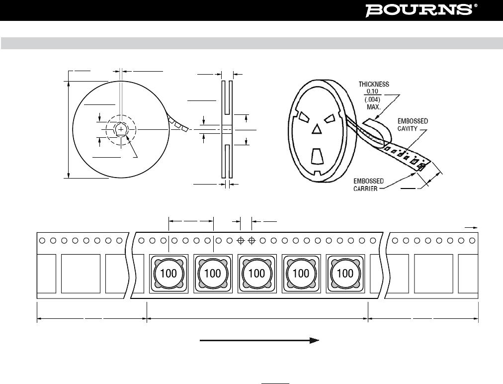
Packaging ....... 400 pcs. per 13-inch reel
Materials
Product Dimensions
Recommended Layout
Electrical Schematic
DIMENSIONS:
MM
(INCHES)
21
34
1
2
3
4
3
DUAL INDUCTOR MODE SERIES MODE
4
2
1
7.6
(.299)
MAX.
7.6
(.299)
MAX.
TYP.
TYP.
0.4
(.016)
2.9
(.114)
1.0
(.039)
1.0
(.039)
1.73
(.068)
7.9
(.311)
0.4
(.016)
1.0
(.039)
1.73
(.068)
7.9
(.311)
3.4 ± 0.2
(.134 ± .008)
2.7
(.106)
TYP.
N2
2
4
N1
1
3
N2
2
4
N1
1
3
N2
2
4
N1
1
3
PARALLEL SERIES
*RoHS COMPLIANT
LEAD FREE
*RoHS COMPLIANT
VERSIONS
AVAILABLE
LEAD FREE
VERSIONS ARE
RoHS COMPLIANT*
How to Order
SRF1260 - 100M
Model
Value Code (see table)
4
3
1
2
12.50
(.492)
MAX.
12.50
(.492)
MAX.
6.00 ± 0.2
(.236 ± .008)
1.80 ± 0.2
(.071 ± .008)
5.00 ± 0.3
(.197 ± .012)
5.00 ± 0.3
(.197 ± .012)
12
34
1
2
43
DUAL INDUCTOR MODE SERIES MODE
2.15
(.085)
2.15
(.085)
1.28
(.050)
1.28
(.050)
4.50
(.177)
4.50
(.177)
13.00
(.512)
13.00
(.512)
220