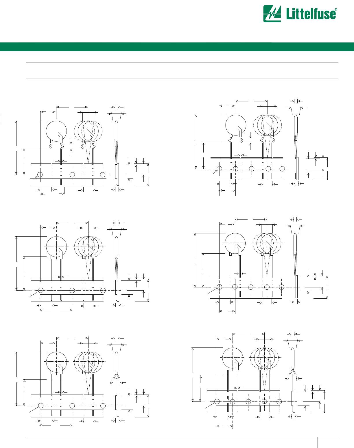
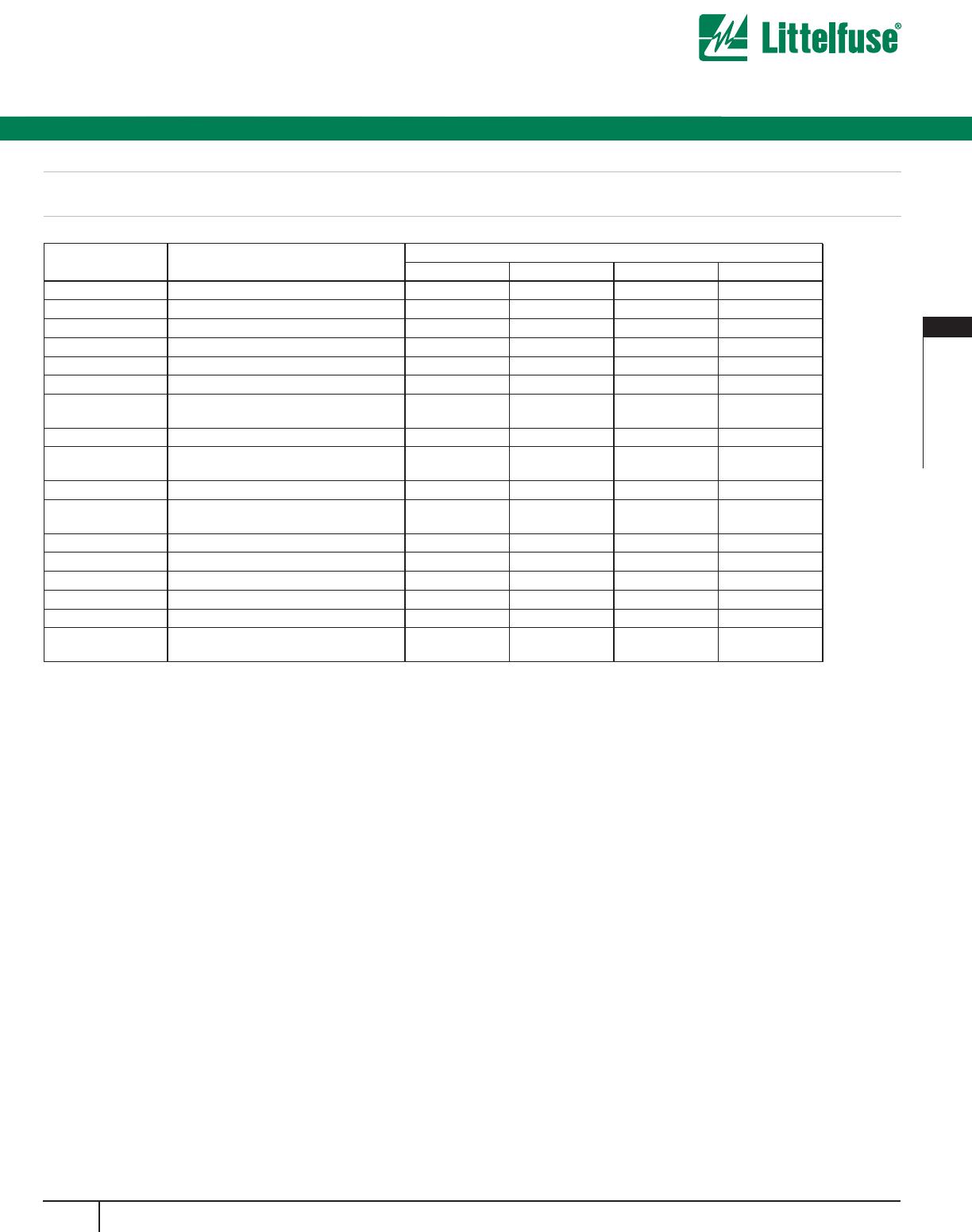
SYMBOL PARAMETER
MODEL SIZE
7mm 10mm 14mm 20mm
P Pitch of Component 12.7 ± 1.0 25.4 ± 1.0 25.4 ± 1.0 25.4 ± 1.0
P
0
F
eed Hole Pitch 12.7 ± 0.2 12.7 ± 0.2 12.7 ± 0.2 12.7 ± 0.2
P
1
Feed Hole Center to Pitch 3.85 ± 0.7 8.85 ± 0.7 8.85 ± 0.7 8.85 ± 0.7
P
2
Hole Center to Component Center 6.35 ± 0.7 12.7 ± 0.7 12.7 ± 0.7 12.7 ± 0.7
F
Lead to Lead Distance 5.0 ± 0.8 7.5 ± 0.8 7.5 ± 0.8 7.5 ± 0.8
h Component Alignment 2.0 Max 2.0 Max 2.0 Max 2.0 Max
W Tape Width 18.0 + 1.0
18.0 - 0.5
18.0 + 1.0
18.0 - 0.5
18.0 + 1.0
18.0 - 0.5
18.0 + 1.0
18.0 - 0.5
W
0
Hold Down Tape Width 12.0 ± 0.3 12.0 ± 0.3 12.0 ± 0.3 12.0 ± 0.3
W
1
H
ole Position 9.0 + 0.75
9.0 - 0.50
9
.0 + 0.75
9.0 - 0.50
9
.0 + 0.75
9.0 - 0.50
9
.0 + 0.75
9.0 - 0.50
W
2
Hold Down Tape Position 0.5 Max 0.5 Max 0.5 Max 0.5 Max
H Height from Tape Center to Component
Base
18.0 + 2.0
18.0 - 0.0
18.0 + 2.0
18.0 - 0.0
18.0 + 2.0
18.0 - 0.0
18.0 + 2.0
18.0 - 0.0
H
0
Seating Plane Height 16.0 ± 0.5 16.0 ± 0.5 16.0 ± 0.5 16.0 ± 0.5
H
1
Component Height 32.0 Max 36.0 Max 40.0 Max 46.5 Max
D
0
Feed Hole Diameter 4.0 ± 0.2 4.0 ± 0.2 4.0 ± 0.2 4.0 ± 0.2
t Total Tape Thickness 0.7 ± 0.2 0.7 ± 0.2 0.7 ± 0.2 0.7 ± 0.2
U
Under-crimp Width 8.0 Max 8.0 Max
p
Component Alignment 3
o
Max
1.00mm
3
o
Max
1.00mm
3
o
Max
1.00mm
3
o
Max
NOTE: Dimensions are in mm.
8.0 Max
8.0 Max