LTC4245
30
4245fa
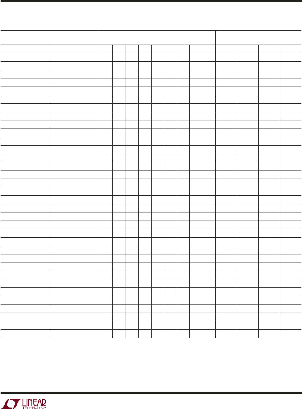
Table 6. LTC4245 Register Address and Contents
REGISTER ADDRESS* REGISTER NAME READ/WRITE DESCRIPTION
DECIMAL HEX
0, 8 00h, 08h STATUS (A) R System Status Information
1, 9 01h, 09h ALERT (B) R/W Controls Which Faults Cause ALERT# Pin to be Pulled Low
2, 10 02h, 0Ah CONTROL (C) R/W Controls Part Behavior Such As Auto-Retry, Sequencing, etc.
3, 11 03h, 0Bh ON (D) D3:D0 R/W**, D7:D4 R Sets State and Reports Status of Switches
4, 12 04h, 0Ch FAULT1 (E) R/W Fault Log for Undervoltage and Overcurrent
5, 13 05h, 0Dh FAULT2 (F) R/W Fault Log for Power Bad, PGI, FET Short, BD_SEL#, GPIO1
6, 14 06h, 0Eh GPIO (G) G2:G0 R, G7:G3 R/W Sets State and Reports Status of GPIO1 to GPIO3 pins, Control
Which Pin is Multiplexed to the GPIO Channel of ADC
7, 15 07h, 0Fh ADCADR (H) R/W 4-Bit ADC Channel Address for On-Demand ADC Measurement
16 10h 12VIN (I) R/W
†
ADC 12V
IN
Voltage Data
17 11h 12VSENSE (J) R/W
†
ADC 12V Current Sense Voltage Data
18 12h 12VOUT (K) R/W
†
ADC 12V
OUT
Voltage Data
19 13h 5VIN (L) R/W
†
ADC 5V
IN
Voltage Data
20 14h 5VSENSE (M) R/W
†
ADC 5V Current Sense Voltage Data
21 15h 5VOUT (N) R/W
†
ADC 5V
OUT
Voltage Data
22 16h 3VIN (O) R/W
†
ADC 3V
IN
Voltage Data
23 17h 3VSENSE (P) R/W
†
ADC 3.3V Current Sense Voltage Data
24 18h 3VOUT (Q) R/W
†
ADC 3V
OUT
Voltage Data
25 19h VEEIN (R) R/W
†
ADC V
EEIN
Voltage Data
26 1Ah VEESENSE (S) R/W
†
ADC –12V Current Sense Voltage Data
27 1Bh VEEOUT (T) R/W
†
ADC V
EEOUT
Voltage Data
28 to 31 1Ch to 1Fh GPIOADC (U) R/W
†
ADC GPIO Voltage Data
All registers are 8-bit wide.
* Register address MSBs b7 – b5 are ignored.
** Cannot set D3:D0 high if bit A1 set.
†
Set bit C7 before writing.
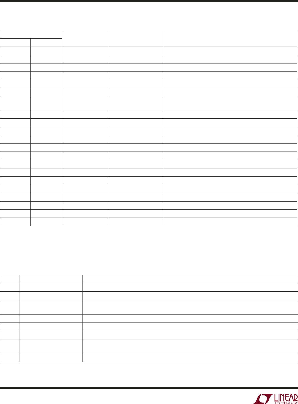
Table 7. STATUS Register A (00h)- Read Only
BIT NAME OPERATION
A7 ADC Busy Indicates State of ADC; 1 = ADC Busy Measuring, 0 = ADC Quiescent
A6 BD_SEL# Input State of the BD_SEL# Pin; 1 =BD_SEL# High, 0 = BD_SEL# Low
A5 FET Short Present Indicates Potential FET Short on at Least One Supply, if ADC Current Sense Voltage Measurement Exceeds 7
LSB While FET is Off; 1 = FET is Shorted, 0 = FET is Not Shorted
A4 LOCAL_PCI_RST# Output LOCAL_PCI_RST# Pin Open-Drain Output State; 1 = High Impedance, 0 = Pulls Low
A3 PCI_RST# Input State of the PCI_RST# Pin; 1 = PCI_RST# High, 0 = PCI_RST# Low
A2 Power Bad Indicates Power Bad Present on at Least One of the Supply Outputs; 1 = Power Bad, 0 = No Power Bad
A1 SS Busy Indicates SS Pin is Being Used to Ramp Up a Supply, Affects Writing to D3:D0 Bits
1 = SS Pin Ramping, Cannot Set D3:D0 High, 0 = SS Pin Reset
A0 Undervoltage Indicates Undervoltage Present on at Least One of the Input Supply; 1 = Undervoltage, 0 = Not Undervoltage
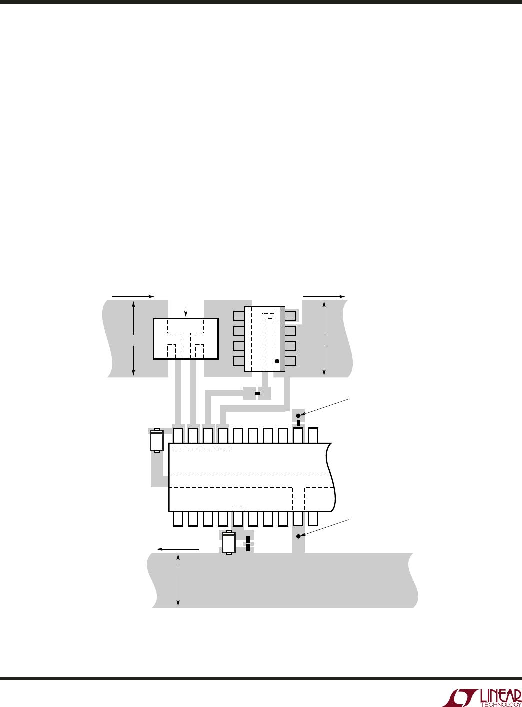
APPLICATIO S I FOR ATIO
WUU
U