-Page2-
Specifications for BNC Connectors
BNC style connectors are miniature, light-weight, weatherproof interconnecting devices characterized by their two-stud, quick disconnect bayonet lock
coupling arrangement. Their design functions satisfactorily from DC to 11 GHz in static applications, or from DC to 4GHz in applications involving
vibration. The connectors typically yield a low VSWR (reflected signal) to 4GHz. Primary applications include radio telecommunications, broadcast
equipment, medical equipment, computer, Precision Video, High definition studio broadcast, video switching and test instrumentation where frequent
coupling and de-coupling are necessary. Bomar’s BNCs are available in an extensive variety of configurations and cable sizes and are impedance
matched to either 50 ohm or 75 ohm.
-Page1-
MATERIALS
Connector Parts Material Equivalent Standard
Connector Body and Parts Brass ISOCuZn38Pb2 Body Part
Male Contact Pin Brass QQ-B-626
Commercial Grade Zinc Alloy/Brass --------------
Outer Contact Brass QQ-B-750
Socket Contact Beryllium Copper QQ-C-530 / MIL-H-7199
---------- Phosphor Copper CuBe2
Crimp Ferrule Annealed Copper QQ-C-576
Insulators, Standard Versions Teflon L-P403 / BS4271
---------- Delrin Grade B
Rubber Gaskets Silicone Rubber ASTM-E1418PSI
Plating Nickel (Silver Optional) MIL-G-45204
ELECTRICAL
Requirement Performance Test † Specification
Impedance
50 75
Frequency Range 0-4GHz 0-1 GHz ------------
VSWR 1.30 Max. MIL-C-39012
RF Insertion Loss 0.2 db Min. at 3 GHz MIL-C-39012
RF Leakage -55 db Min. at 3 GHz MIL-C-39012
Test Voltage ( At Sea Level) 1500V rms MIL-STD-202
Working Voltage ( At Sea Level ) 500V rms MIL-STD-202
Insulation Resistance 5000 Meg ohms Min. MIL-STD-202
Contact Resistance 3 Milli ohms Max. MIL-C-39012
MECHANICAL & ENVIRONMENTAL
Requirement Performance Test † Specification
Durability 500 Insertions & Extractions Min. MIL-C-39012
Shock 50 G MIL-STD-202
Vibration 20 G from 80-2000 Hz MIL-STD-202
Cable Retention (Cable Types) 60 lbs. Minimum Pull Test MIL-C-39012
Coupling Nut 60 lbs. Maximum MIL-C-39012
Temperature Range
Teflon: -55 to +199 C ------------
Delrin: -40 to +85 C ------------
Moisture Resistance Continuous Test MIL-STD-202
Salt Spray 48 Hours MIL-STD-202
†Products are made to conform to the Mil standard but are for commercial applications and are not QPL
FOR TECHNICAL SUPPORT: PHONE 973-347-4040 / FAX973-347-2111 Back to Index
1
BNC 3 Piece Crimp
-Page 2-
- Page 3 -
s
s
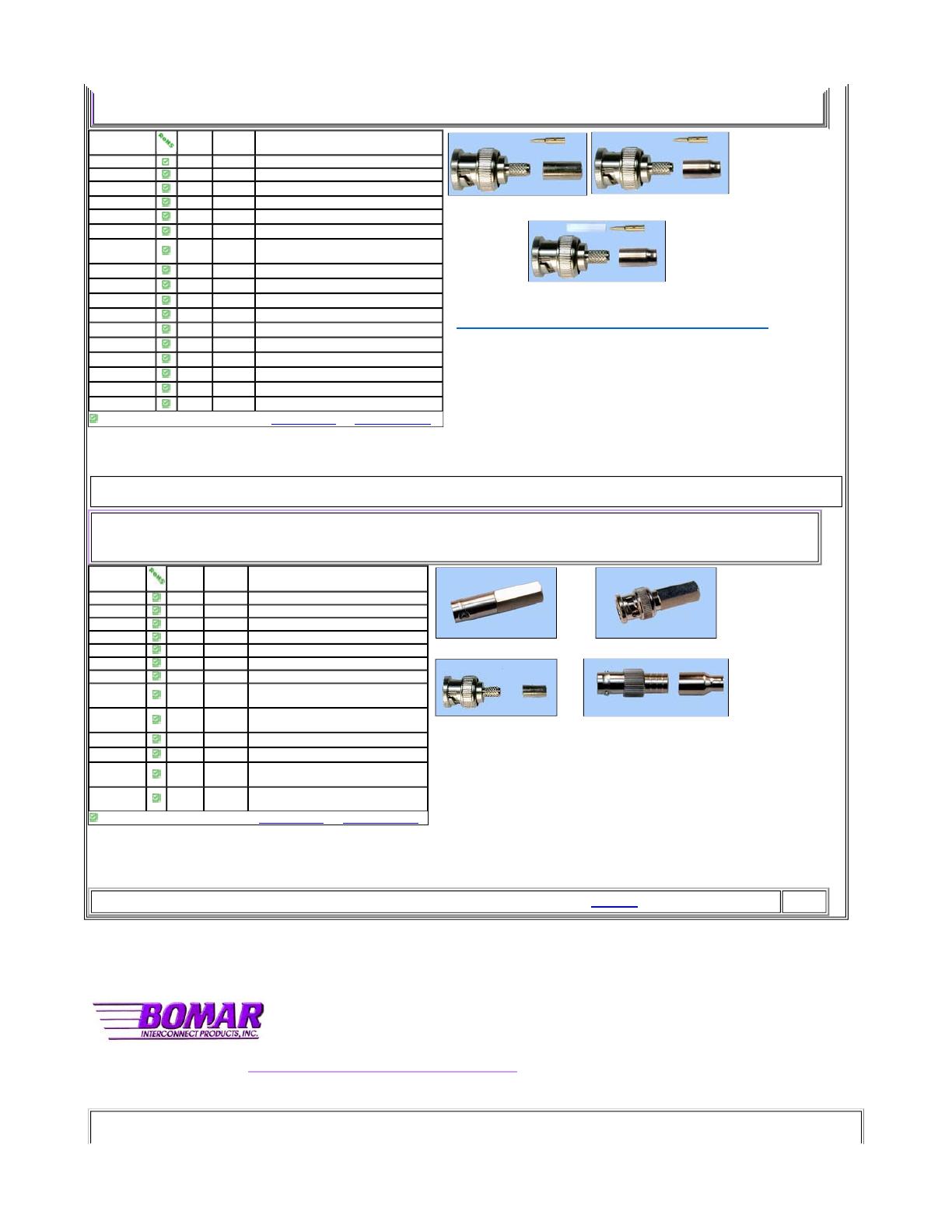
BNC three piece crimp connectors feature semi-captive contacts that “click” into place assuring perfect installation. Each crimp pin has a vent hole for optional
soldering. Soldering is recommended for all stranded conductors 26 AWG or smaller.
Part Number
(Male)
(I.D.)
**
Fig. No. RG/U Cable
310A205A .200 In. Fi
g
. 1 6, 21 AWG Center Conducto
r
310A205A18 .200 In. Fi
g
. 1 6 CATV, 18 AWG Center Conducto
r
310A205F .124 In. Fig. 1 58A/U, 58C/U Stranded, 141, Thin PVC
310A205FS .124 In. Fi
g
. 1 58/U Solid Conducto
r
310A205FV .125 In. Fig. 2 58/U Thin-Net Plenum
310A205FV2 .125 In. Fig. 2 Mini 59, RGB Cable (23 AWG)
310A205FV3
.125 In. Fig. 2 Mini 59, RGB Cable (26 AWG)
310A204G .150 In. Fig. 1 59, 62, 210
310A205G20 .150 In. Fig. 1 RG59 20 AWG Center Cond.
310A205G23 .150 In. Fig. 1 Belden 8241
310A205MV .125 In. Fig. 3
174, 178, 196, Mini RGB Cable 50
310B205MV .125 In. Fig. 3
174, 178, 196, Mini RGB Cable 75
310A205N .090 In. Fig. 3 179, 187
310A205P .125 In. Fig. 1 223
310B205Q .205 In. Fig. 1 Belden 8281 True 75 Ohms
310A204T .150 In. Fig. 2 59, 62, Plenum
310A208W2 .103 In. Fig.1 Mini 59, RGB Cable (26 AWG)
RoHS compliant ** crimp shank REQUEST QUOTE REQUEST DRAWING
Fig.1 Fig.2
Fig.3
Click Here for Connector Dimensions/Stripping Dimensions
BNC Twist-On and 2 Piece Crimp
BNC Twist-On connectors are field installable and require no tooling other than a stripping tool for the cable preparation. The center conductor is inserted into Bomar’s
unique Posi-Con ™contact, as the connector is twisted onto the cable’s outer jacket.
BNC 2 Piece crimp connectors make use of a fully captivated pin. Just insert the center conductor into the connector body, slide the ferrule over the braid, and apply a single
hex-crimp to the ferrule. These connectors are easy to install and reliable and are recommended only for the lower data transmission speeds.
Part
Number
Gender
Fig.
No.
RG/U Cable
310A405A Male Fi
g
. 8 6, Thick ne
t
310A405F Male Fig. 8 58A/U Solid Cond, 141, Thin PVC
310A405F1 Male Fi
g
. 8 58/U Solid Cond. -.172"- .178 “
310A405F2 Male Fi
g
. 8 58/U Thin Plenum - .158" - .162"
310A405F3 Male Fi
g
. 8 Thin Plenum .150"
310A405G Male Fi
g
. 8 59, 62, 210 PVC
310A405T Male Fi
g
. 8 59, 62, 210 Plenum
320A405F
Female
Fig. 8A 58 Solid (PVC)
320A405G
Female
Fig. 8A 59, 62, 210 (PVC)
310X205F Male Fig. 6 RG58 (PVC)
310X205G Male Fig. 6 RG59, 62 (PVC)
320X205F
Female
Fig. 7 RG58 (PVC)
320X205G
Female
Fig. 7 RG59, 62 (PVC)
RoHS compliant REQUEST QUOTE REQUEST DRAWING
Fig.8A
Fig.8
Fig.6 Fig.7
FOR TECHNICAL SUPPORT: PHONE 973-347-4040 / FAX973-347-2111 Back to Index
2
BNC Connectors
BNC Standard Clamp
BNC standard clamp style is a simplified version of the original military clamp style. It is required that the contact be soldered to the center conductor
RoHS compliant REQUEST QUOTE REQUEST DRAWING
s
s
s
s
s
s
s
s
s
RoHS compliant
REQUEST QUOTE
REQUEST DRAWING
of the cable.
Part
Number
Gender Fig. No. RG/U Cable
310A105A Male 9 6
310A105D Male 9 11A
310A105F Male 9 58, 58A, 58C, 141
310A105G Male 9 59, 62, 210
310A105M Male 9 174, 188, 316
320A105F* Female N/S 58, 58A, 58C, 141
320A105G* Female N/S 59, 62, 214
Figure 9
BNC Specialty Broadcast Plugs Click here for complete Broadcast Catalog
Broadcast grade BNC connectors are perfectly matched to 75 ohm impedance’s. The superior plugs are for studio wiring and other broadcast uses. Solid
precision machined brass, not die-cast, hold up under the toughest conditions. Here, we are showing the eight most popular but there are many more
versions matched to the popular cable manufacturer’s part number.
Part Number Gender Belden Cable
SBC1505A Male 1505A
SBC1694A Male 1694A
SBC1695A Male 1695A
SBC1855A Male 1855A
SBC7731A Male 7731A
SBC8218 Male 8218
SBC8241 Male 8241
SBC8281 Male 8281
RoHS compliant REQUEST QUOTE REQUEST DRAWING
BNC Bulkhead Jacks
Versions are available for front mounting, (F/M) rear mounting, (R/M) crimp types, bulkhead mount grounded, or bulkhead mount, isolated. (Color-
coded available.) These jacks are held into the panel by a hex-nut and lock washer. All units feature nickel plated, brass bodies, and gold phosphor-
bronze contacts
Figure 13 Figure 14
Figure 15 Figure 16
Part Number Description
Fig
No.
Hole
ID
Dwg
321A245A R/M Crimp, RG6 13 .500
321A245F R/M Crimp, RG58 , Thin-net PVC 13 .500
321A245FV R/M Crimp, Thin-Net Plenum 13 .500
321A245G R/M Crimp, RG59, 62, 210 13 .500
321A245M R/M Crimp, RG174, 188, 196, 316 13 .500
321B245M* R/M Crimp, RG174, 188, 196, 316 13 .500
321B245N* R/M Crimp, RG179, 187 N/S .500
326A515 F/M Solder (Grounded) 14 .375
326R515 F/M Solder (Isolated) White Bushing 15 .375
326R515RD F/M Solder (Isolated) Red Bushing 16 .375
326R515GN F/M Solder (Isolated) Green Bushing 16 .375
326R515BL F/M Solder (Isolated) Blue Bushing 16 .375

361V704EFTW

Mfr. #:
Manufacturer:
Bomar Interconnect
Description:
RF Connectors / Coaxial Connectors BNC V-BITE W/FLANG
Lifecycle:
New from this manufacturer.
Delivery:
DHL FedEx Ups TNT EMS
Payment:
T/T Paypal Visa MoneyGram Western Union