LTC2927
13
2927fb
Final Sanity Checks
The collection of equations below is useful for identifying
unrealizable solutions.
As stated in step 2, the slave supply must fi nish ramping
before the master signal has reached its fi nal voltage. This
can be verifi ed by the following equation:
V
R
R
V
TRACK
TB
TA
MASTER
1+
⎛
⎝
⎜
⎞
⎠
⎟
<
Here, V
TRACK
= 0.8V. V
MASTER
is the fi nal voltage of the
master signal (V
CC
if RAMP pin).
It is possible to choose resistor values that require the
LTC2927 to supply more current than the Electrical Char-
acteristics table guarantees. To avoid this condition, check
that I
TRACK
does not exceed 1mA and I
RAMPBUF
does not
exceed ±2mA.
To confi rm that I
TRACK
< 1mA, the TRACK pin’s maximum
guaranteed current, verify that:
V
RR
mA
TRACK
TA TB
< 1
Finally, check that the RAMPBUF pin will not be forced to
sink more than 2mA when it is at 0V or be forced to source
more than 2mA when it is at V
MASTER
.
V
R
mA and
V
RR
mA
TRACK
TB
MASTER
TA TB
<
+
<22
ON Pin Resistive Divider
Check that the ON pin voltage is above the 1.25V maximum
threshold at the lowest possible supply voltage value.
R
R
V
V
ONB
ONA
CC MIN
<
()
.
–
125
1
Also check that the supply voltage is above the minimum
LTC2927 operating supply voltage of 2.9V before the ON
pin is above the 1.21V minimum threshold voltage.
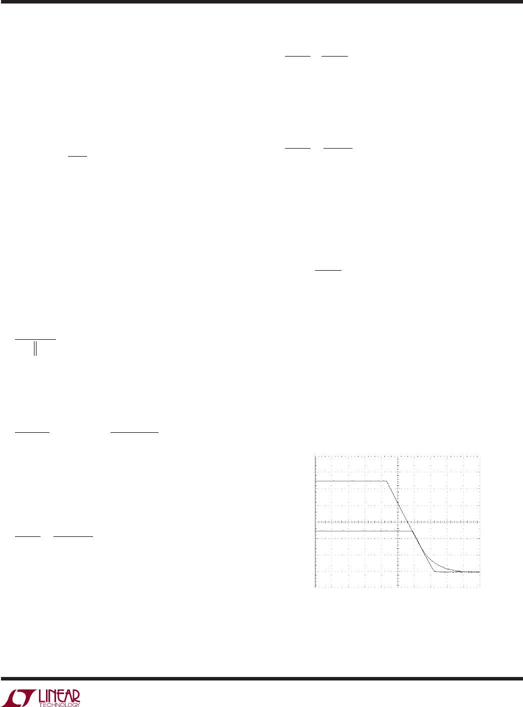
Figure 17. Weak Resistive Load
2927 F17
10ms/DIV
1V/DIV
MASTER
SLAVE
R
R
V
V
ONB
ONA
<
29
121
1
.
.
–
For example, if the typical application shown on page 1
has a 3.3V ±10% V
IN
, the lowest possible operating supply
voltage will be 2.97.
R
R
V
V
ONB
ONA
>=
297
125
1 1 376
.
.
–.
If R
ONA
is 100k then R
ONB
must be greater than 137.6k.
Therefore, 138k is chosen. These values must be checked
to ensure the supply reaches the LTC2927 minimum op-
erating supply voltage of 2.9V before the ON pin is above
the minimum threshold.
138
29
121
1 1 389.
.
.
–.<=
V
V
Load Requirements
When the supply is ramped down quickly, either the load
or the supply itself must be capable of sinking enough
current to support the ramp rate. For example, if there
is a large output capacitance on the supply and a weak
resistive load, supplies that do not sink current will have
their falling ramp rate limited by the RC time constant of
the load and the output capacitance. Figure 17 shows the
case when the slave supply does not track the master
near ground.
APPLICATIO S I FOR ATIO
WUU
U