Expand menu
Hello, Sign in
My Account
0
Cart
Home
Products
Sensors
Semiconductors
Passive Components
Connectors
Power
Electromechanical
Optoelectronics
Circuit Protection
Integrated Circuits - ICs
Main Products
Manufacturers
Blog
Services
About OMO
About Us
Contact Us
Check Stock
ASMT-JY32-NWY01
P1-P3
P4-P6
P7-P9
P10-P12
P13-P13
7
Solder Pad
Solder Pad
Slug Indepdent
0.80
0.85
1.75
1.30
ø
1.90
3.50
5.20
Figure 14. Recommended pick and place nozzle tip
. Inner diameter = 3.2 mm
(Acc. to J-STD-020C)
217°C
200°C
60 - 120 SEC.
6°C/SEC. MAX.
3°C/SEC. MAX.
3°C/SEC. MAX.
150°C
255 - 260°C
100 SEC. MAX.
10 - 30 SEC.
TIME
TEMPERATURE
Figure 15. Recommended Reow Soldering Prole
Note:
For detail inf
ormation on reow soldering of A
vago surface mount LEDs, do refer to A
vago Application Note AN1060 Surface Mounting SMT LED
Indicator Components.
ø
3.2
Figure 13. Recommended soldering land patt
ern
8
Option Selec
tion Details
ASMT
-J x
1
3 2 – x
2
x
3
x
4
x
5
x
6
x
3
– Minimum Flux Bin Selection
x
4
– Maximum Flux Bin Selection
x
5
– Color Bin Selection
x
6
– P
ackaging Option
Flux Bin Limit [x
3
, x
4
]
Bin ID
Luminous Flux (lm) at 350 mA
Min.
Max.
U
87.4
99.6
V
99.6
113.6
W
113.6
129.5
X
129.5
147.7
Y
147.7
168.4
Cool White
Selec
tion
Bin ID
0
F
ull Distribution
E
VM, UM,
VN and UN
F
WM, VM, WN
and VN
G
XM, WM,
XN and WN
H
UN, VN,
U0 and V0
J
WN, VN, W0
and V0
K
XN, WN,
X0 and W0
L
V0, U0, VP and UP
M
W0, V0, WP
, VP
and WQ
N
X0, W0, XP
, WP
and WQ
P
Y0
Q
YA
W
arm White
Selec
tion
Bin ID
0
F
ull Distribution
E
NM, MM, N1 and M1
F
PM, NM, P1 and N1
G
QM, PM, Q1 and P1
H
M1, N1, M0 and N0
J
P1, N1, P0 and N0
K
Q1, P1, Q0 and P0
L
N0, M0, NA and MA
M
P0, N0, P
A and NA
N
Q0, P0, QA and P
A
Neutral White
Selec
tion
Bin ID
0
F
ull Distribution
E
SM, RM, S1 and R1
F
TM, SM,
TN and S1
G
S1, R1, S0 and R0
H
TN, S1,
T0 and S0
J
S0, R0, SA and RA
K
T0, S0,
TP and SA
Color Bin Selec
tion [x
5
]
Individual reel will contain parts from one color bin selection only
.
9
0.26
0.28
0.30
0.32
0.34
0.36
0.38
0.40
0.42
0.26
0.28
0.30
0.32
0.34
0.36
0.38
0.40
X-COORDINATE
Y-COORDINATE
10000K
7000K
6300K
5000K
4500K
Y0
YA
UM
UN
UP
V0
VM
VN
VP
X0
XP
XM
XN
W0
WQ
0.32
0.34
0.36
0.38
0.40
0.42
0.44
0.46
0.34
0.36
0.38
0.40
0.42
0.44
X-COORDINATE
Y-COORDINATE
RM
R1
R0
RA
T0
SM
S1
SA
TM
TN
TP
S0
4500K
0.32
0.34
0.36
0.38
0.40
0.42
0.44
0.46
0.48
0.38
0.40
0.42
0.44
0.46
0.48
0.50
X-COORDINATE
Y-COORDINATE
QM
MM
NM
Q1
QA
P1
M0
M1
MA
NA
3050K
2850K
3500K
3250K
2700K
PM
Q0
P0
PA
BLACK BODY CURVE
N1
N0
U0
WM
WN
WP
5650K
BLACK BODY CURVE
BLACK BODY CURVE
4100K
3800K
3500K
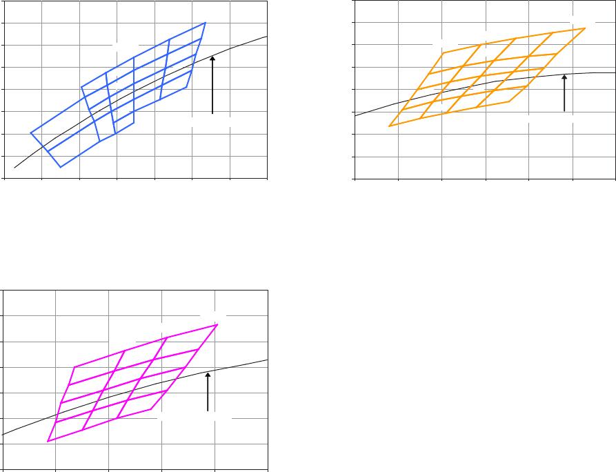
Figure 16. Color bin Structure for Cool White
Figure 17. Color bin structure for W
arm White
Figure 18. Color bin structure for Neutral Whit
e
P1-P3
P4-P6
P7-P9
P10-P12
P13-P13
ASMT-JY32-NWY01
Mfr. #:
Buy ASMT-JY32-NWY01
Manufacturer:
Broadcom / Avago
Description:
High Power LEDs - White 3W Warm White SMD
Lifecycle:
New from this manufacturer.
Delivery:
DHL
FedEx
Ups
TNT
EMS
Payment:
T/T
Paypal
Visa
MoneyGram
Western
Union
Products related to this Datasheet
ASMT-JN32-NVW01
ASMT-JN32-NWX01
ASMT-JW32-NUV01
ASMT-JN32-NWXG1
ASMT-JW32-NWXH1
ASMT-JN32-NWXH1
ASMT-JW32-NWXJ1
ASMT-JW32-NWXK1
ASMT-JW32-NVVJ1
ASMT-JW32-NWX01
ASMT-JW32-NVV01
ASMT-JW32-NVW01
ASMT-JN32-NVV01
ASMT-JY32-NUW01
ASMT-JY32-NTVK1
ASMT-JW32-NWY01
ASMT-JY32-NWY01
ASMT-JN32-NUV01
ASMT-JY32-NTVJ1
ASMT-JY32-NUWJ1
ASMT-JY32-NUWK1
ASMT-JN32-NVVH1
ASMT-JY32-NUWH1
ASMT-JN32-NVVG1
ASMT-JW32-NVVH1
ASMT-JW32-NVVK1
ASMT-JY32-NTV01
ASMT-JY32-NTVH1