Accu-P
®
Environmental / Mechanical Characteristics
QUALITY & RELIABILITY
Accu-P
®
is based on well established thin-film technology
and materials.
• ON-LINE PROCESS CONTROL
This program forms an integral part of the production cycle
and acts as a feedback system to regulate and control
production processes. The test procedures, which are
integrated into the production process, were developed
after long research work and are based on the highly
developed semiconductor industry test procedures and
equipment. These measures help AVX to produce a con-
sistent and high yield line of products.
• FINAL QUALITY INSPECTION
Finished parts are tested for standard electrical parameters
and visual/mechanical characteristics. Each production lot
is 100% evaluated for: capacitance and proof voltage at
2.5 U
R
. In addition, production is periodically evaluated for:
Average capacitance with histogram printout for
capacitance distribution;
IR and Breakdown Voltage distribution;
Temperature Coefficient;
Solderability;
Dimensional, mechanical and temperature stability.
QUALITY ASSURANCE
The reliability of these thin-film chip capacitors has been
studied intensively for several years. Various measures
have been taken to obtain the high reliability required today
by the industry. Quality assurance policy is based on well
established international industry standards. The reliability
of the capacitors is determined by accelerated testing
under the following conditions:
Life (Endurance) 125°C, 2U
R
, 1000 hours
Accelerated Damp
Heat Steady State 85°C, 85% RH, U
R
,
1000 hours.
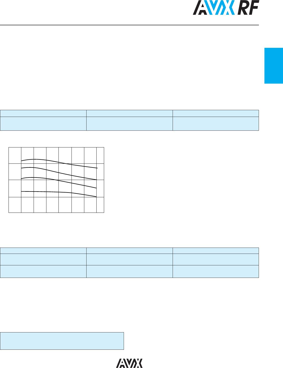
TEST CONDITIONS REQUIREMENT
Life (Endurance)
125°C, 2U
R
,1000 hours No visible damage
MIL-STD-202F Method 108A
Δ C/C ≤ 2% for C≥5pF
Δ C ≤ 0.25pF for C<5pF
Accelerated Damp
85°C, 85% RH, U
R
, 1000 hours No visible damage
Heat Steady State
Δ C/C ≤ 2% for C≥5pF
MIL-STD-202F Method 103B
Δ C ≤ 0.25pF for C<5pF
Temperature Cycling
-55°C to +125°C, 15 cycles – Accu-P
®
No visible damage
MIL-STD-202F Method 107E
Δ C/C ≤ 2% for C≥5pF
MIL-STD-883D Method 1010.7
Δ C ≤ 0.25pF for C<5pF
Resistance to Solder Heat
260°C ± 5°C for 10 secs C remains within initial limits
IEC-68-2-58
ENVIRONMENTAL CHARACTERISTICS
TEST CONDITIONS REQUIREMENT
Solderability
Components completely immersed in a Terminations to be well tinned, minimum 95%
IEC-68-2-58
solder bath at 235°C for 2 secs. coverage
Leach Resistance
Components completely immersed in a
Dissolution of termination faces ≤15% of area
IEC-68-2-58
solder bath at 260±5°C for 60 secs.
Dissolution of termination edges ≤25% of length
Adhesion
A force of 5N applied for 10 secs. No visible damage
MIL-STD-202F Method 211A
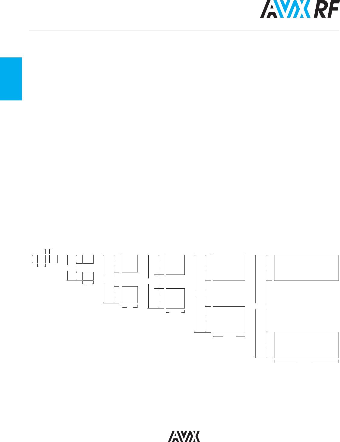
Termination Bond Strength
Tested as shown in diagram No visible damage
IEC-68-2-21 Amend. 2
Δ C/C ≤ 2% for C≥5pF
Δ C ≤ 0.25pF for C<5pF
Robustness of Termination
A force of 5N applied for 10 secs. No visible damage
IEC-68-2-21 Amend. 2
High Frequency Vibration
55Hz to 2000Hz, 20G No visible damage
MIL-STD-202F Method 201A,
204D
(Accu-P
®
only)
Storage
12 months minimum with components Good solderability
stored in “as received” packaging
MECHANICAL CHARACTERISTICS
D
45mm 45mm
D = 3mm Accu-P
D = 1mm Accu-F
1
26