3
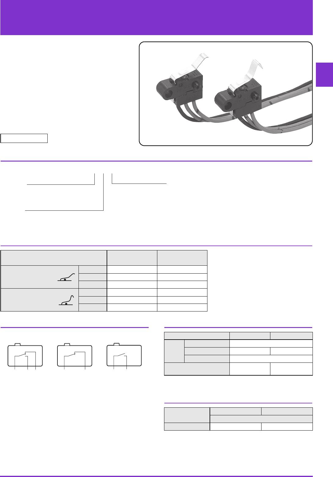
D2FW-G M4 Mounting Sealed Basic Switch
Precautions
★Please refer to "Basic Switches Common Precautions" for correct use.
Use the Switch within the specified Voltage rating. Using the
Switch outside of the rated values will not only shorten its
durability but may cause heat generation or fire damage. When
turning the power ON or OFF, use the rated voltage and current.
●Degree of Protection
Do not use the Switch underwater.
The Switch was tested and found to meet the conditions
necessary to meet the following standards. The test checks for
water intrusion after immersion for a specified time period, not for
switching operation underwater.
JIS C0920:
Degrees of protection provided by enclosures of electrical
apparatus (IP Code)
IEC 60529:
Degrees of protection provided by enclosures (IP Code)
Degree of protection: IP67
(check water intrusion after immersion
for 30 min. submerged 1m underwater)
●Protection Against Chemicals
Prevent the Switch from coming into contact with oil or
chemicals.
Otherwise, damage to or deterioration of Switch materials may
result.
●Mounting
• Turn OFF the power supply before mounting or removing the
Switch, wiring, or performing maintenance or inspection.
Failure to do so may result in electric shock or burning.
• Use M4 mounting screws with plane washers or spring
washers to securely mount the Switch. Tighten the screws to a
torque of 1.18 to 1.47N·m {12 to 15 kgf·cm}.
●Switch Mounting
When mounting the Switch, do not apply force to the actuator in
any direction other than its operating direction.
●Operation
Make sure that the switching object is perfectly separated from
the actuator when it is at the free position and the actuator is
pressed appropriately by the switching object when the switch is
operated.
The switching object must not move beyond its total travel
position, otherwise the Switch may be damaged.
Install the switching object so that its moving direction is the
same as that of the actuator.
●Using Micro Loads
• Even when using micro load models within the operating
range shown below, if inrush/surge current occurs, it may
increase the contact wear and so decrease durability.
Therefore, insert a contact protection circuit where necessary.
• The minimum applicable load is the N-level reference value.
This value indicates the malfunction reference level for the
reliability level of 60% (λ
60).
(JIS C5003)
The equation, λ
60=0.5×10
-6
/operations, indicates that the
estimated malfunction rate is less than operations
with a reliability level of 60%.
Cautions Correct Use
30
24
12
5
0
1 10 100 1,000
Current (mA)
0.1
Operating
range for
general-load
models
D2FW-G2#
Operating range
for micro load
models
D2FW-G0#
16.6 mA0.16 mA 100 mA
1mA
Voltage (V)