AS218-321LF

1
Skyworks Solutions, Inc. • Phone [781] 376-3000 • Fax [781] 376-3100 • sales@skyworksinc.com • www.skyworksinc.com
200082 Rev. D • Skyworks Proprietary Information • Products and Product Information are Subject to Change Without Notice. August 9, 2006
Applications
WLAN 802.11a, b, g diversity
Features
Operating frequency 0.1–6 GHz
Positive low voltage control (0/3 V operation)
Low insertion loss
Available lead (Pb)-free and RoHS-compliant MSL-1 @ 250 °C
per JEDEC J-STD-020
Description
The AS218-321 is a broadband transfer switch designed to
combine T/R and antenna diversity switching functions on a
single IC. The device is designed to handle high power and
maintain high linearity at low control voltages. This low-cost
switch is ideal for Wi-Fi systems and is capable of covering
both the 2.4 and 5 GHz bands.
AS218-321, AS218-321LF: PHEMT GaAs IC High-Power
Transfer Switch 0.1–6 GHz
DATA SHEET
Skyworks offers lead (Pb)-free, RoHS (Restriction of
Hazardous Substances)-compliant packaging.
NEW
Parameter
(1, 4)
Condition Frequency Min. Typ. Max. Unit
Insertion loss
(2)
Ant 1, Ant 2 to Tx, Rx 0.10–6.00 GHz 1.6 1.8 dB
2.40–2.50 GHz 1.2 1.4 dB
5.15–5.85 GHz 1.4 1.6 dB
Isolation Ant 1, Ant 2 to Tx, Rx 0.10–6.00 GHz 17 19 dB
2.40–2.50 GHz 26 28 dB
5.15–5.85 GHz 17 19 dB
Return loss
(3)
Ant 1, Ant 2 to Tx, Rx 0.10–6.00 GHz 10 dB
2.40–2.50 GHz 15 dB
5.15–5.85 GHz 20 dB
Electrical Specifications at 25 °C (0, 3 V)
1. All measurements made in a 50 system.
2. Insertion loss changes by 0.003 dB/C.
3. Return loss for insertion loss state.
4. Tx and Rx paths can be used interchangeably.
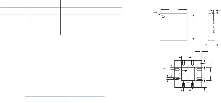
Pin Out (Top View)
GND
GND
V
1
GND
GND
V
2
TX
GND
R
X
Ant 1
GND
Ant 2
123
456
12 11 10
987
C
BL
C
BL
C
BL
C
BL
DC blocking capacitors (C
BL
) required on RF ports.
C
BL
= 15 pF.
Typical Performance Data (0, +3 V)
Insertion Loss (dB)
Frequency (GHz)
Insertion Loss vs. Frequency
-2.0
-1.8
-1.6
-1.4
-1.2
-1.0
-0.8
-0.6
-0.4
-0.2
0
0.6 1.2 1.8 2.4 3.0 3.6 4.2 4.8 5.4 6.0
A1-RX Path
A1-TX Path
A2-RX Path
A2-TX Path
Isolation (dB)
Frequency (GHz)
Isolation vs. Frequency
-40
-35
-30
-25
-20
-15
-10
-5
0
0.6 1.2 1.8 2.4 3.0 3.6 4.2 4.8 5.4 6.0
A1-RX Path
A1-TX Path
A2-RX Path
A2-TX Path
A1-A2
TX-RX
Return Loss (dB)
Frequency (GHz)
Return Loss vs. Frequency
-50
-45
-40
-35
-30
-25
-20
-15
-10
-5
0
0.6 1.2 1.8 2.4 3.0 3.6 4.2 4.8 5.4 6.0
A1-RX Path
A1-TX Path
A2-RX Path
A2-TX Path
Characteristic Value
RF input power 35 dBm > 500 MHz
0/7 V control
Control voltage -0.2 V, +8 V
Operating temperature -40 °C to +85 °C
Storage temperature -65 °C to +150 °C
Absolute Maximum Ratings
Skyworks Solutions, Inc. • Phone [781] 376-3000 • Fax [781] 376-3100 • sales@skyworksinc.com • www.skyworksinc.com
August 9, 2006 • Skyworks Proprietary Information • Products and Product Information are Subject to Change Without Notice. • 200082 Rev. D
DATA SHEET • AS218-321, AS218-321LF
2
Parameter Condition Frequency Min. Typ. Max. Unit
2nd and 3rd harmonic 23 dBm input @ 0,3 V 2–6 GHz 63 dBc
P
1 dB
2–6 GHz 33 dBm
IIP3 20 dBm per tone 2–3 GHz 54 dBm
22 dBm per tone 5–6 GHz 47 dBm
Thermal resistance 25 °C/W
Control voltages V
LOW
= 0–0.2 V @ 20 µA max.
V
HIGH
= 3–5 V @ 200 µA max.
Operating Characteristics at 25 °C (0, 3 V)
Performance is guaranteed only under the conditions listed in the specifications table and is
not guaranteed under the full range(s) described by the Absolute Maximum specifications.
Exceeding any of the absolute maximum/minimum specifications may result in permanent
damage to the device and will void the warranty.
CAUTION: Although this device is designed to be as robust as
possible, ESD (Electrostatic Discharge) can damage
this device. This device must be protected at all times
from ESD. Static charges may easily produce poten-
tials of several kilovolts on the human body or
equipment, which can discharge without detection.
Industry-standard ESD precautions must be employed
at all times.
DATA SHEET • AS218-321, AS218-321LF
Skyworks Solutions, Inc. • Phone [781] 376-3000 • Fax [781] 376-3100 • sales@skyworksinc.com • www.skyworksinc.com
200082 Rev. D • Skyworks Proprietary Information • Products and Product Information are Subject to Change Without Notice. August 9, 2006 3
“1” = 3 to 5 V.
“0” = 0 to 0.2 V.
V
1
V
2
Insertion Loss Path
0 1 Ant 1 to Tx, Ant 2 to Rx
1 0 Ant2toTx,Ant1 toRx
0 0 Allowed but not recommended
1 1 Allowed but not recommended
Truth Table QFN-12
0.008 (0.20 mm)
Seating Plane
0.118 (3.00 mm)
Pin 1 Indicator
Pin 1
Indicator
0.118
(3.00 mm)
0.001
(0.02 mm)
0.030
(0.75 mm)
± 0.002
(0.05 mm)
Exposed pad
0.029
(0.73 mm)
0.017
(0.435 mm) Sq.
0.007
(0.180 mm)
0.0196
(0.50 mm) BSC
0.057 (1.45 mm) Sq.
+ 0.004 (0.10 mm)
- 0.006 (0.15 mm)
0.022 (0.55 mm)
± 0.004 (0.10 mm)
0.009 (0.23 mm)
+ 0.003 (0.07 mm)
- 0.002 (0.05 mm)
Recommended Solder Reflow Profiles
Refer to the “Recommended Solder Reflow Profile”
Application Note.
T
ape and Reel Information
Refer to the “Discrete Devices and IC Switch/Attenuators
Tape and Reel Package Orientation” Application Note.

AS218-321LF

Mfr. #:
Manufacturer:
Skyworks Solutions, Inc.
Description:
RF Switch ICs .1-6.0GHz GaAs IL1.6dB
Lifecycle:
New from this manufacturer.
Delivery:
DHL FedEx Ups TNT EMS
Payment:
T/T Paypal Visa MoneyGram Western Union

Products related to this Datasheet