MMKP 383
Vishay BCcomponents
AC and Pulse Double Metallized Polypropylene
Film Capacitors MMKP Radial Potted Type
www.vishay.com For technical questions, contact: dc-film@vishay.com
Document Number: 28124
208 Revision: 19-Mar-13
This document is subject to change without notice.
THE PRODUCTS DESCRIBED HEREIN AND THIS DOCUMENT ARE SUBJECT TO SPECIFIC DISCLAIMERS, SET FORTH AT www.vishay.com/doc?91000
Not Recommended for New Design, Use New MMKP383
6. When using these capacitors as across-the-line capacitor in the input filter for mains applications or as series connected with
an impedance to the mains the applicant must guarantee that the following conditions are fulfilled in any case (spikes and
surge voltages from the mains included).
Voltage Conditions for 6 Above
EXAMPLE
C = 4 nF - 1600 V used for the voltage signal shown in next drawing.
U
P-P
= 1000 V; U
P
= 900 V; T
1
= 12 µs; T
2
= 64 µs; T
3
= 4 µs
The ambient temperature is 80 °C. In case of failure, the oscillation is blocked.
Checking conditions:
1. The peak voltage U
P
= 900 V is lower than 1600 Vdc
2. The peak-to-peak voltage 1000 V is lower than 22 x 550 Vac = 1600 U
P-P
3. The voltage pulse slope (dU/dt) = 1000 V/4 µs = 250 V/µs
This is lower than 8000 V/µs (see specific reference data for each version)
4. The dissipated power is 35 mW as calculated with fourier terms and typical tgd.
The temperature rise for W
max.
= 6.0 mm and pitch = 15 mm will be 35 mW/11 mW/°C = 3.2 °C
This is lower than 10 °C temperature rise at 80 °C, according graph.
5. Oscillation is blocked
6. Not applicable
Voltage Signal
ALLOWED VOLTAGES
T
amb
85 °C 85 °C < T
amb
105 °C
Maximum continuous RMS voltage U
Rac
U
Rac
Maximum temperature RMS-overvoltage (< 24 h) 1.25 x U
Rac
1.25 x U
Rac
Maximum peak voltage (V
O-P
) (< 2 s)
1.6 x U
Rdc
1.1 x U
Rdc
Voltage
U
p
T
3
T
1
T
2
U
p-p
Time
Document Number: 28124 For technical questions, contact: dc-film@vishay.com
www.vishay.com
Revision: 19-Mar-13 209
MMKP 383
AC and Pulse Double Metallized Polypropylene
Film Capacitors MMKP Radial Potted Type
Vishay BCcomponents
This document is subject to change without notice.
THE PRODUCTS DESCRIBED HEREIN AND THIS DOCUMENT ARE SUBJECT TO SPECIFIC DISCLAIMERS, SET FORTH AT www.vishay.com/doc?91000
Not Recommended for New Design, Use New MMKP383
INSPECTION REQUIREMENTS
General Notes:
Sub-clause numbers of tests and performance requirements refer to the “Sectional Specification, Publication IEC 60384-17 and
Specific Reference Data”.
Group C Inspection Requirements
SUB-CLAUSE NUMBER AND TEST CONDITIONS PERFORMANCE REQUIREMENTS
SUB-GROUP C1A PART OF SAMPLE
OF SUB-GROUP C1
4.1 Dimensions (detail) As specified in chapters “General Data” of
this specification
4.3.1 Initial measurements Capacitance
Tangent of loss angle:
For C 1 µF at 100 kHz or
for C > 1 µF at 10 kHz
4.3 Robustness of terminations Tensile: Load 10 N; 10 s
Bending: Load 5 N; 4 x 90°
No visible damage
4.4 Resistance to soldering heat Method: 1A
Solder bath: 280 °C ± 5 °C
Duration: 10 s
4.14 Component solvent resistance Isopropylalcohol at room temperature
Method: 2
Immersion time: 5 min ± 0.5 min
Recovery time: Min. 1 h, max. 2 h
4.4.2 Final measurements Visual examination No visible damage
Legible marking
Capacitance C/C| 1 % of the value measured initially
Tangent of loss angle Increase of tan
0.0005 for: C 100 nF or
0.001 for: 100 nF < C 470 nF or
0.0015 for: C 470 nF
Compared to values measured in 4.3.1
SUB-GROUP C1B OTHER PART OF
SAMPLE OF SUB-GROUP C1
4.6.1 Initial measurements Capacitance
Tangent of loss angle:
For C 1 µF at 100 kHz or
for C > 1 µF at 10 kHz
4.15 Solvent resistance of the marking Isopropylalcohol at room temperature
Method: 1
Rubbing material: cotton wool
No visible damage
Legible marking
4.6 Rapid change of temperature Immersion time: 5.0 min ± 0.5 min
A = - 55 °C
B = + 105 °C
5 cycles
Duration t = 30 min
4.7 Vibration Visual examination
Mounting: see section “Mounting” for more
information
Procedure B4
Frequency range: 10 Hz to 55 Hz
Amplitude: 0.75 mm or
Acceleration 98 m/s²
(whichever is less severe)
Total duration 6 h
No visible damage
MMKP 383
Vishay BCcomponents
AC and Pulse Double Metallized Polypropylene
Film Capacitors MMKP Radial Potted Type
www.vishay.com For technical questions, contact: dc-film@vishay.com
Document Number: 28124
210 Revision: 19-Mar-13
This document is subject to change without notice.
THE PRODUCTS DESCRIBED HEREIN AND THIS DOCUMENT ARE SUBJECT TO SPECIFIC DISCLAIMERS, SET FORTH AT www.vishay.com/doc?91000
Not Recommended for New Design, Use New MMKP383
SUB-GROUP C1B OTHER PART OF
SAMPLE OF SUB-GROUP C1
4.7.2 Final inspection Visual examination No visible damage
4.9 Shock Mounting:
See section “Mounting” for more information
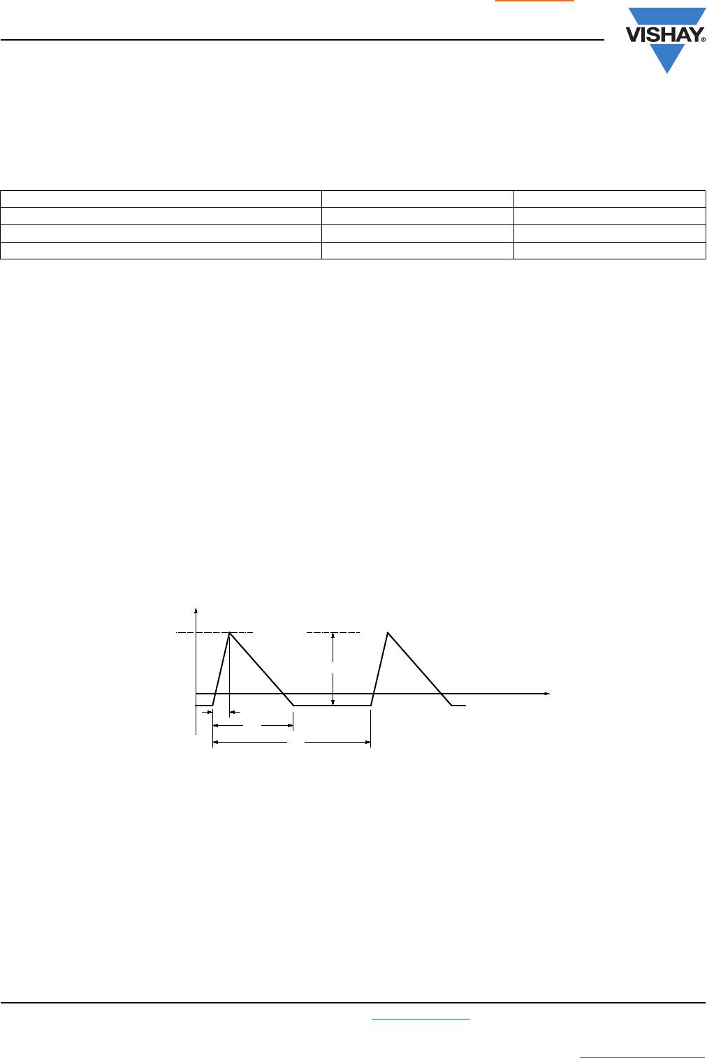
Pulse shape: Half sine
Acceleration: 490 m/s²
Duration of pulse: 11 ms
4.9.3 Final measurements Visual examination No visible damage
Capacitance C/C| 1 % of the value measured in 4.6.1
Tangent of loss angle Increase of tan
0.0005 for: C 100 nF or
0.001 for: 100 nF < C 470 nF or
0.0015 for: C 470 nF
Compared to values measured in 4.6.1
Insulation resistance As specified in section “Insulation
Resistance” of this specification
SUB-GROUP C1 COMBINED SAMPLE OF
SPECIMENS OF SUB-GROUPS
C1A AND C1B
4.10 Climatic sequence
4.10.2 Dry heat Temperature: + 105 °C
Duration: 16 h
4.10.3 Damp heat cyclic
Test Db, first cycle
4.10.4 Cold Temperature: - 55 °C
Duration: 2 h
4.10.6 Damp heat cyclic
Test Db, remaining cycles
4.10.6.2 Final measurements Voltage proof = U
Rdc
for 1 min within 15 min
after removal from testchamber
No breakdown of flash-over
Visual examination No visible damage
Legible marking
Capacitance For original pitch = 22.5 mm and 27.5 mm:
C/C| 3 % of the value measured in
4.4.2 or 4.9.3
Tangent of loss angle Increase of tan
0.0005 for: C 100 nF or
0.001 for: 100 nF < C 470 nF or
0.0015 for: C 470 nF
Compared to values measured in 4.3.1 or
4.6.1
Insulation resistance 50 % of values specified in section
“Insulation Resistance” of this specification
SUB-GROUP C2
4.11 Damp heat steady state 56 days, 40 °C, 90 % to 95 % RH
no load
4.11.1 Initial measurements Capacitance
Tangent of loss angle at 1 kHz
4.11.3 Final measurements Voltage proof = U
Rdc
for 1 min within 15 min
after removal from testchamber
No breakdown of flash-over
Visual examination No visible damage
Legible marking
Capacitance |C/C| 1 % of the value measured in
4.11.1.
Tangent of loss angle Increase of tan
0.0005 for: C 100 nF or
0.001 for: 100 nF < C 470 nF or
0.0015 for: C 470 nF
Compared to values measured in 4.11.1
Insulation resistance 50 % of values specified in section
“Insulation Resistance” of this specification
SUB-CLAUSE NUMBER AND TEST CONDITIONS PERFORMANCE REQUIREMENTS

BFC238310114

Mfr. #:
Manufacturer:
Vishay
Description:
Film Capacitors .11uF 5% 400volts
Lifecycle:
New from this manufacturer.
Delivery:
DHL FedEx Ups TNT EMS
Payment:
T/T Paypal Visa MoneyGram Western Union