8Mb
SMART 3 BOOT BLOCK FLASH MEMORY
09005aef81136a91 Micron Technology, Inc., reserves the right to change products or specifications without notice.
Q10.fm - Rev. E 6/04 EN
18 ©2001 Micron Technology, Inc. All rights reserved.
Absolute Maximum Ratings*
Voltage on VCC Supply
Relative to V
SS . . . . . . . . . . . . . . . . . . . . . -0.5V to +4V**
Input Voltage Relative to V
SS. . . . . . . . . . . -0.5V to +4V**
V
PP Voltage Relative to VSS. . . . . . . . . . . . -0.5V to +5.5V†
RP# or A9 Pin Voltage
Relative to V
SS . . . . . . . . . . . . . . . . . . -0.5V to +12.6V††
Temperature Under Bias . . . . . . . . . . . . . -10ºC to +80ºC
Storage Temperature (plastic). . . . . . . . -55ºC to +125ºC
Power Dissipation . . . . . . . . . . . . . . . . . . . . . . . . . . . . . . 1W
*Stresses greater than those listed under “Absolute
Maximum Ratings” may cause permanent damage to
the device. This is a stress rating only, and functional
operation of the device at these or any other condi-
tions above those indicated in the operational sections
of this specification is not implied. Exposure to abso-
lute maximum rating conditions for extended periods
may affect reliability.
**V
CC, input and I/O pins may transition to -2V for
<20ns and V
CC + 2V for <20ns.
†
Voltage may pulse to -2V for <20ns and 7V for <20ns.
††
Voltage may pulse to -2V for <20ns and 14V for
<20ns.
NOTE:
1. All voltages referenced to VSS.
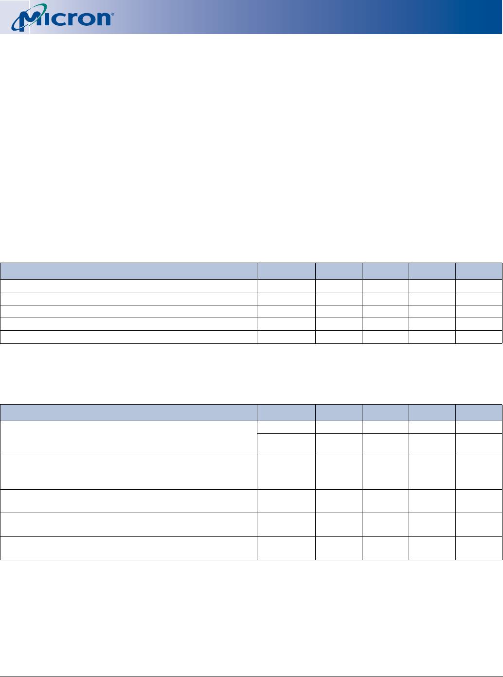
Table 8: Electrical Characteristics and Recommended DC READ Operating
Conditions
Commercial Temperature (0°C ≤ T
A
≤ +70°C) and Extended Temperature (-40°C ≤ T
A
≤ +85°C)
PARAMETER/CONDITION SYMBOL MIN MAX UNITS NOTES
3.3V Supply Voltage
V
CC 33.6V 1
Input High (Logic 1) Voltage, all inputs
V
IH 2.4 Vcc + 0.5 V 1
Input Low (Logic 0) Voltage, all inputs
V
IL -0.5 0.8 V 1
Device Identification Voltage, A9
V
ID 10 12.6 V 1
V
PP Supply Voltage
VPP -0.5 5.5 V 1
Table 9: DC Operating Characteristics
Commercial Temperature (0°C ≤ T
A
≤ +70°C) and Extended Temperature (-40°C ≤ T
A
≤ +85°C)
PARAMETER/CONDITION SYMBOL MIN MAX UNITS NOTES
OUTPUT VOLTAGE LEVELS
Output High Voltage (IOH = -100µA)
Output Low Voltage (IOL = 2mA)
V
OH Vcc - 0.2 – V 1
V
OL –0.45V
INPUT LEAKAGE CURRENT
Any input (0V ≤ VIN ≤ Vcc);
All other pins not under test = 0V
I
L -1 1 µA
INPUT LEAKAGE CURRENT: A9 INPUT
(10V ≤ A9 ≤ 12V = V
ID)
I
ID –500µA
INPUT LEAKAGE CURRENT: RP# INPUT
(10V ≤ RP# ≤ 12V = V
HH)
I
HH –500µA
OUTPUT LEAKAGE CURRENT
(D
OUT is disabled; 0V ≤ VOUT ≤ Vcc)
I
OZ -10 10 µA