Grayhill, Inc. • 561 Hillgrove Avenue • LaGrange, Illinois 60525-5997 • USA • Phone: 708-354-1040 • Fax: 708-354-2820 • www.grayhill.com
Joysticks
Joysticks
* Exceeding the Absolute Maximum Voltage may result in permanent damage to the device. This is a stress rating only and functional operation of the device at those or any other conditions
above those indicated in the operation listings of this specication is not implied.
SPECIFICATIONS
General Electrical Specications
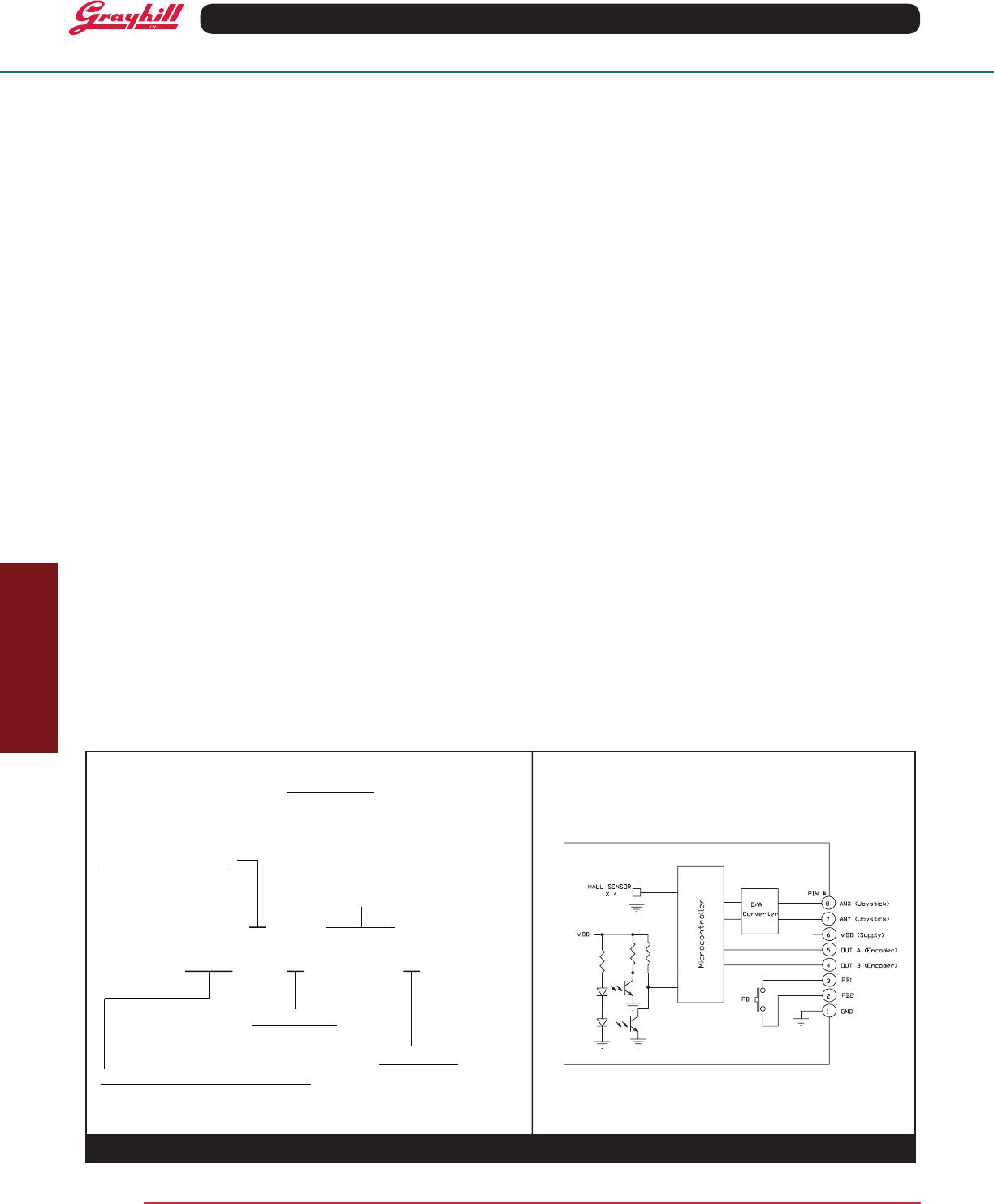
Operating Voltage on Pin 6 (VDD): 5.0 ±
0.25V
Absolute Maximum Voltage* on Pin 6
(VDD): -0.3 V min, 6.5 V max.
Operating Current: 8 mA typ., 12 mA, max.
Joystick Electrical and Mechanical
Ratings
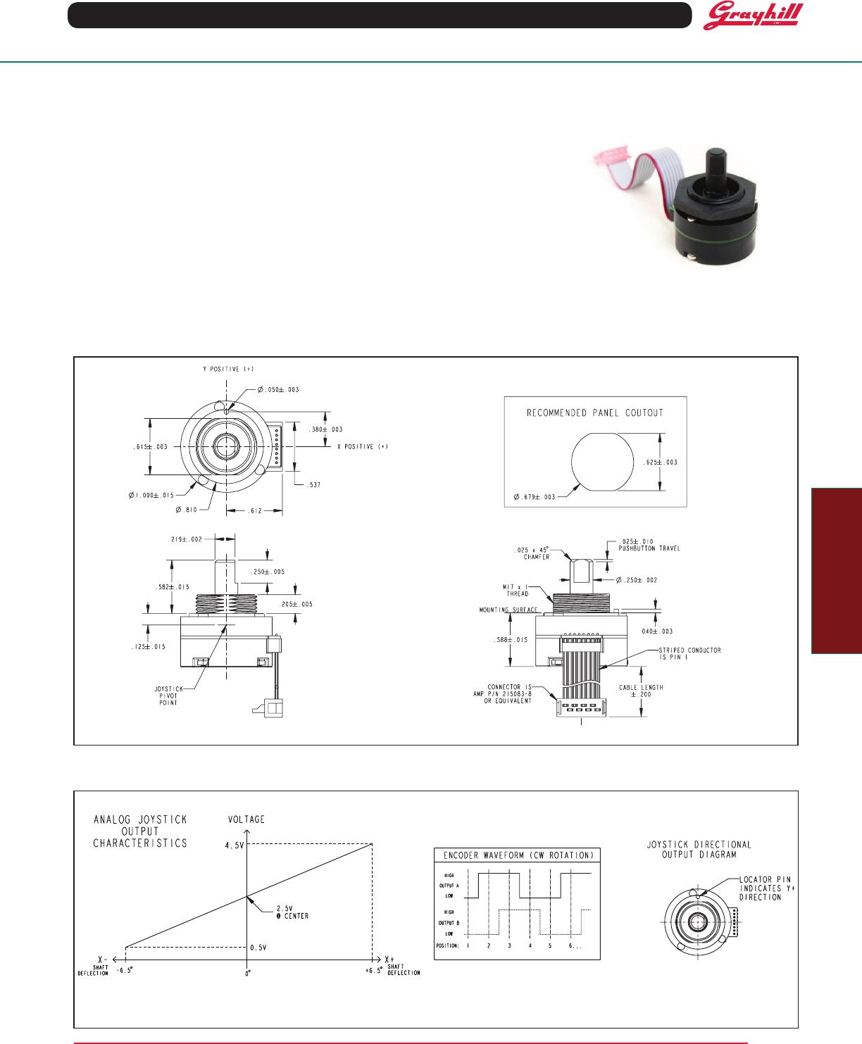
Sensing Method: Hall effect, proportional
to angle of deection
Output Voltage (Pins 7 & 8): Analog (Ratio-
metric to Operating Voltage)
Output at Center Position: 50% VDD
Output at Full Travel:
10% VDD (for X-, Y- directions)
90% VDD (for X+, Y+ directions)
Output Tolerance: ± 2% VDD (at Center
and at Full Travel)
Output Current: 200 µA, max.
Angle of Throw: 6.5° + 2° / -1° in main
directions; 9.0° ± 0.1° in diagonals
Life: 500,000 actuations in each of the four
main directions
Pushbutton Electrical and
Mechanical Ratings
Rating: 10 mA at 5 Vdc resistive
Absolute Maximum Voltage* on Pins 2 &
3: 6.0 V
Contact Resistance: less than 10 ohms
Life: 1 million actuations minimum
Contact Bounce: < 4 mS make, <10 mS
break
Actuation Force: 960 ± 150 grams (700
grams Dome)
Pushbutton Travel: 0.025 ± 0.010 inches
Rotary Electrical and Mechanical
Ratings
Output Code (Pins 4 & 5): 2-Bit quadrature:
Channel "A" leads channel "B" by 90° elec-
trically during clockwise rotation of the shaft
Output Type: Push/Pull
Output Low Voltage: 0.6V maximum for
IOL = 2 mA.
Output High Voltage: 4.3V minimum for
IOH = -1.5 mA, (VDD = 5.0V)
Mechanical Life: 1 million rotational cycles
of operation (1 cycle is a rotation through all
positions and a full return)
Mounting Torque: 15 in-oz maximum
Shaft Push-Out Force: 45 lbs minimum
Shaft Pull-Out Force: 45 lbs minimum
Solderability: 95% free of pin holes and
voids
Detents: 20 Position
Torque: Initially 3.5 ± 1.5 in-oz average of all
positions, with a 1.5 in-oz maximum range
(Max position - Min position) = Range
After 1 million cycles, average torque shall
not change by more than 50% of the initial
value
Soldering Recommendation
Hand solder only per IPC J-STD-001
Environmental Ratings
Operating Temperature Range: -40°C to
85°C
Storage Temperature Range: -55°C to
100°C
Relative Humidity: 96 hours at 90-95%
humidity at 40°C
Vibration: Harmonic motion with amplitude of
15g, within a varied 10 to 2000 Hz frequency
for 12 hours
Mechanical Shock:
Test 1: 100g for 6ms half-sine wave with a
velocity change of 12.3 ft/s
Test 2: 100g for 6ms sawtooth wave with a
velocity change of 9.7 ft/s
Materials and Finishes
Pin Header: Terminals: Phosphor bronze;
Insulator: Nylon 4/6; Plated with tin
Cable: Copper stranded with silver plating in
PVC insulation, 28 AWG
Connector: Nylon 4/6; 30% Glass-lled ; Tin-
plated phosphor bronze terminals
Mounting Nut: Polyurethane
Shaft: Thermoplastic
ROHS Compliant.
EMC Ratings
Radiated Immunity: Passed 10 V/m: 80-2700
MHz per IEC 61000-4-3
Conducted Immunity: Passed 10 V/m: 0.15
80 MHz per IEC 61000-4-6
Radiated Emissions: Passed EN 55022
Class B
Conducted Emissions: Passed EN 55022
Class B
Electrostatic Discharge: Passed 15kV
contact/25kV air discharge per IEC 61000-4-2
Power Frequency Magnetic Field: Passed
30 A/m per IEC 61000-4-8
ORDERING INFORMATION
For prices and custom congurations, contact a local sales ofce, an authorized distributor, or Grayhill's sales department.
67CXX-X-X-XXXX
FORCE OPTION
M = Medium Forces
JOYSTICK DIRECTIONS
8 = 4 Sensors, 8 Directions
(No Gating)
020 = 2"
040 = 4”
060 = 6”
2” Increments
TERMINATION
S = Stripped Cable
C = Cable with Connector
P = Pin Header
ROTATIONAL ENCODER RESOLUTION
18 = 18°, 20 positions
08 = Non-detent, 20 positions
Leave blank if choosing pin header
Examples:
67C18-8-M-020 = 2.0” cable with connecto
67C18-8-M-P = Pin header
BLOCK DIAGRAM