LT6000/LT6001/LT6002
600012fa
6
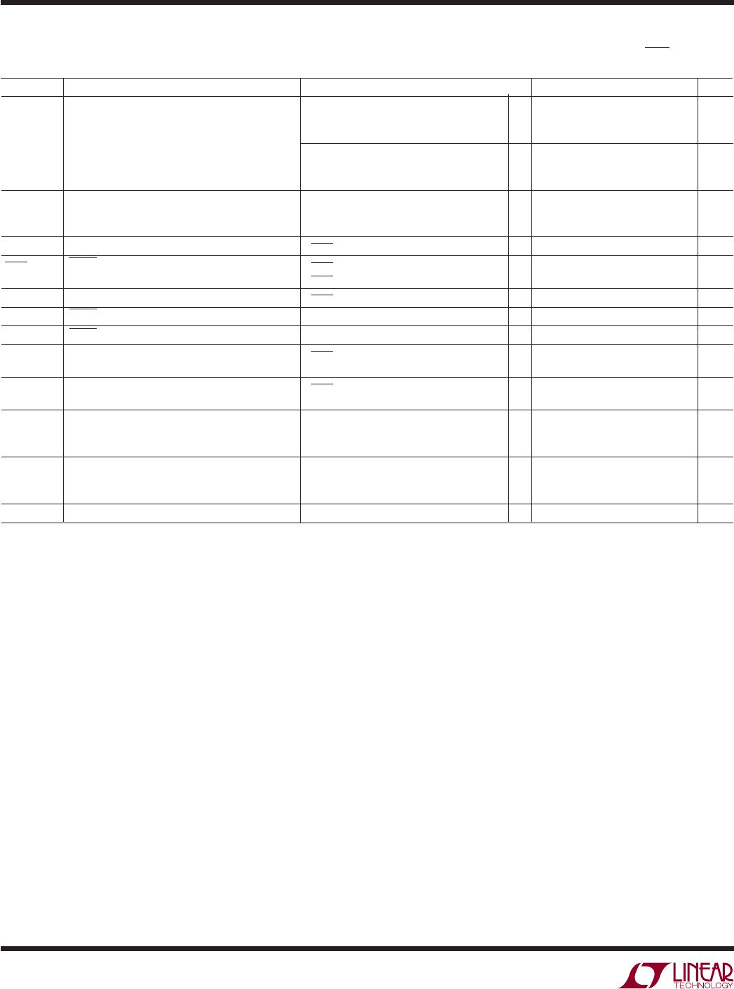
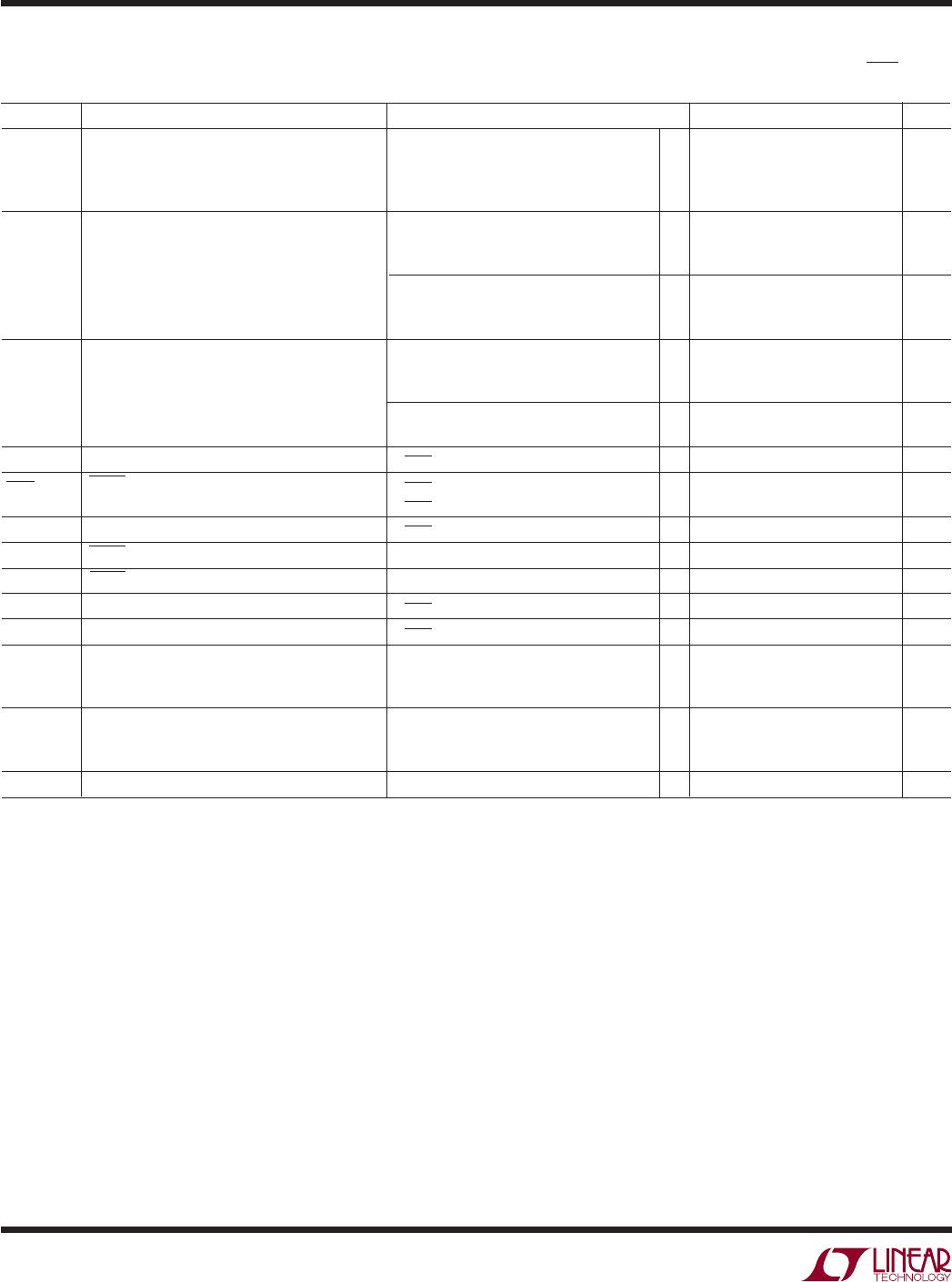
ELECTRICAL CHARACTERISTICS
The ● denotes specifications which apply over the full specified temperature
range, otherwise specifications are T
A
= 25°C. V
S
= 5V, 0V, V
CM
= V
OUT
= 1/2 Supply. For the LT6000 and the LT6001DD, V
SHDN
= V
+
,
unless otherwise noted.
SYMBOL PARAMETER CONDITIONS MIN TYP MAX UNITS
V
OH
Output Swing High (Note 6) Input Overdrive = 30mV
No Load
● 30 60 mV
I
SOURCE
= 100µA ● 140 225 mV
R
L
= 10k to GND ● 160 400 mV
I
SC
Short-Circuit Current Short to GND 5 10 mA
0°C ≤ T
A
≤ 70°C ● 4mA
–40°C ≤ T
A
≤ 85°C ● 3mA
Short to V
+
3.5 7.5 mA
0°C ≤ T
A
≤ 70°C ● 2.5 mA
–40°C ≤ T
A
≤ 85°C ● 1.5 mA
I
S
Supply Current per Amplifier 15 18 µA
0°C ≤ T
A
≤ 70°C ● 24 µA
–40°C ≤ T
A
≤ 85°C ● 27 µA
V
S
= ±8V 20 25 µA
● 34 µA
Total Supply Current in Shutdown (Note 7) V
SHDN
= 0.3V ● 35 µA
I
SHDN
SHDN Pin Current (Note 7) V
SHDN
= 5V ● 030 nA
V
SHDN
= 0V ● –1000 –650 nA
Shutdown Output Leakage Current (Note 7) V
SHDN
= 0.3V (V
–
≤ V
OUT
≤ V
+
) ● 20 nA
V
L
SHDN Pin Input Low Voltage (Note 7) ● 0.3 V
V
H
SHDN Pin Input High Voltage (Note 7) ● 4.7 V
t
ON
Turn On Time (Note 7) V
SHDN
= 0V to 5V, R
L
= 10k 400 µs
t
OFF
Turn Off Time (Note 7) V
SHDN
= 5V to 0V, R
L
= 10k 100 µs
GBW Gain Bandwidth Product Freq = 1kHz 40 60 kHz
0°C ≤ T
A
≤ 70°C ● 35 kHz
–40°C ≤ T
A
≤ 85°C ● 30 kHz
SR Slew Rate A
V
= –1, V
OUT
= 0.5V to 4.5V 11 18 V/ms
Measure 1V to 4V, 0°C ≤ T
A
≤ 70°C ● 8 V/ms
–40°C ≤ T
A
≤ 85°C ● 6 V/ms
FPBW Full Power Bandwidth (Note 9) V
OUT
= 4V
P-P
0.87 1.4 kHz
Note 1: Stresses beyond those listed under Absolute Maximum Ratings
may cause permanent damage to the device. Exposure to any Absolute
Maximum Rating condition for extended periods may affect device
reliability and lifetime.
Note 2: A heat sink may be required to keep the junction temperature
below the absolute maximum. This depends on the power supply voltage
and how many amplifiers are shorted. The θ
JA
specified for the DD and
DHC packages is with minimal PCB heat spreading metal. Using expanded
metal area on all layers of a board reduces this value.
Note 3: The LT6000C/LT6000I/LT6001C/LT6001I and LT6002C/LT6002I
are guaranteed functional over the temperature range of –40°C to 85°C.
Note 4: The LT6000C/LT6001C/LT6002C is guaranteed to meet specified
performance from 0°C to 70°C. The LT6000C/LT6001C/LT6002C are
designed, characterized and expected to meet specified performance from
–40°C to 85°C but are not tested or QA sampled at these temperatures.
The LT6000I/LT6001I/ LT6002I is guaranteed to meet specified
performance from –40°C to 85°C.
Note 5: This parameter is not 100% tested.
Note 6: Output voltage swings are measured between the output and
power supply rails.
Note 7: Specifications apply to the LT6000 or the LT6001DD with
shutdown.
Note 8: Guaranteed by correlation to slew rate at V
S
= 1.8V and GBW at
V
S
= 5V.
Note 9: Full-power bandwidth is calculated from the slew rate:
FPBW = SR/πV
P-P
.