MBRB10150CT

MBRB10150CT
ADVANCED INFORMATION
10A SCHOTTKY BARRIER RECTIFIER
Product Summary
MBRB10150CT (Per Leg)
Description
This Schottky Barrier Rectifier is
designed to meet the stringent
requirements of Commercial Applications.
Polarity Protection Diode
Re-Circulating Diode
Switching Diode
V
RRM
(V) I
O
(A)
V
F
(MAX)
(V)
@ +25°C
I
R
(MAX)
(mA)
@ +25°C
150
5
0.89
0.05
Features and Benefits
Guard Ring Die Construction for Transient Protection
High Surge Current Capability
Low Forward Voltage Drop
Lead-Free Finish; RoHS Compliant (Notes 1 & 2)
Halogen and Antimony Free. “Green” Device (Note 3)
Qualified to AEC-Q101 Standards for High Reliability
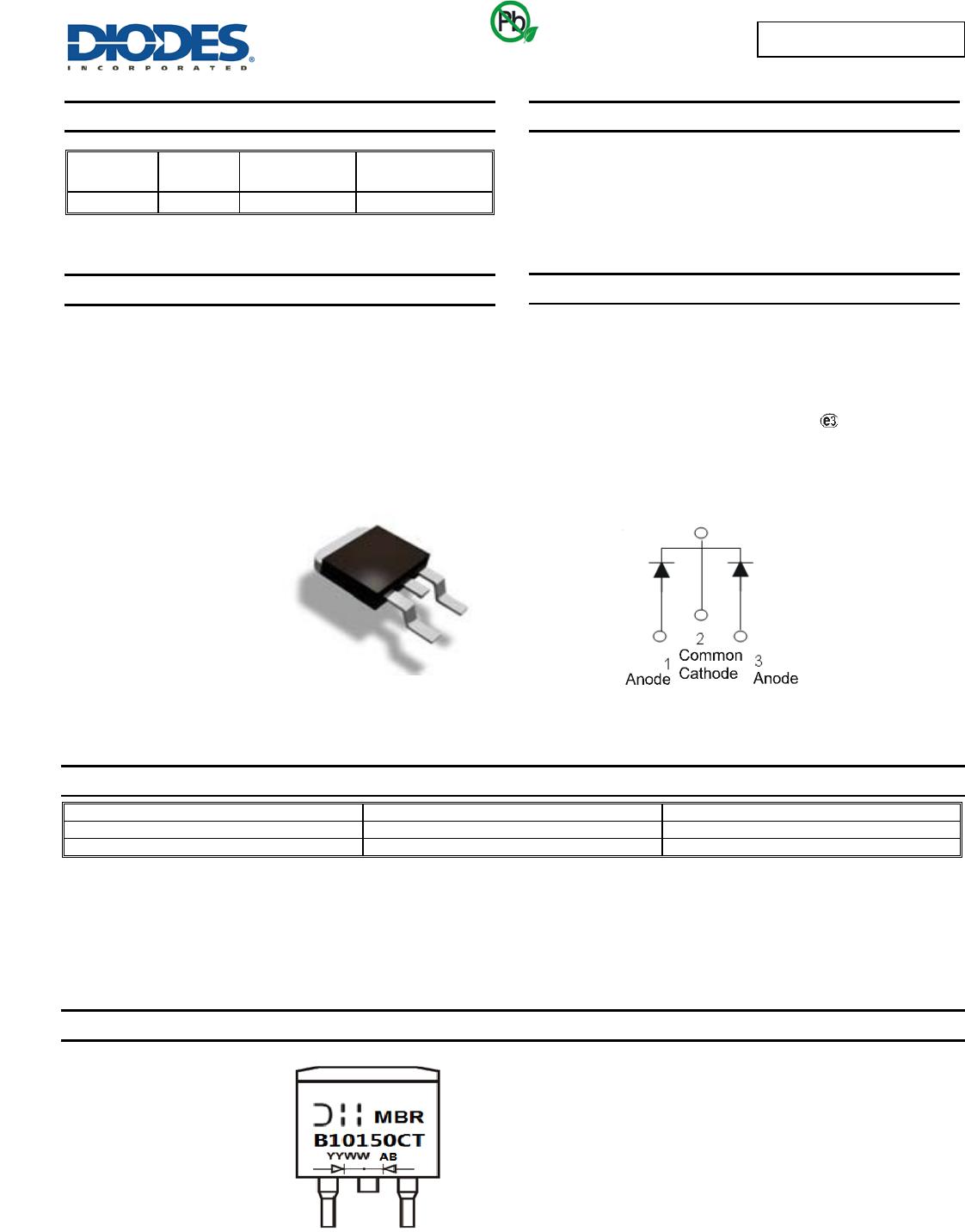
Mechanical Data
Case: TO263AB (D2PAK)
Case Material: Molded Plastic, “Green” Molding Compound.
UL Flammability Classification Rating 94V-0
Moisture Sensitivity: Level 1 per J-STD-020
Terminals: Finish - Matte Tin Annealed over Copper Leadframe.
Solderable per MIL-STD-202, Method 208
Polarity: See Below
Weight: TO263AB 1.6 grams (Approximate)
Ordering Information (Note 4)
Case
TO263AB (D2PAK)
TO263AB (D2PAK)
Notes: 1. EU Directive 2002/95/EC (RoHS) & 2011/65/EU (RoHS 2) compliant. All applicable RoHS exemptions applied.
2. See http://www.diodes.com/quality/lead_free.html for more information about Diodes Incorporated’s definitions of Halogen- and Antimony-free, "Green"
and Lead-free.
3. Halogen- and Antimony-free "Green” products are defined as those which contain <900ppm bromine, <900ppm chlorine (<1500ppm total Br + Cl) and
<1000ppm antimony compounds.
4. For packaging details, go to our website at http://www.diodes.com/products/packages.html.
Marking Information
Package Pin Out
TO263AB
MBRB10150CT = Product Type Marking Code
AB
= Foundry and Assembly Code
YYWW = Date
Code Marking
YY = Last
Two Digits of Year (ex: 14 = 2014)
WW = Week (01
- 53)
Green
MBRB10150CT
Document number: DS37111 Rev. 4 - 2
1 of 5
www.diodes.com
September 2014
© Diodes Incorporated
MBRB10150CT
ADVANCED INFORMATION
Maximum Ratings (Per Leg) (@T
A
= +25°C, unless otherwise specified.)
Single phase, half wave, 60Hz, resistive or inductive load.
For capacitance load, derate current by 20%.
Characteristic
Symbol
Value
Unit
Peak Repetitive Reverse Voltage
Working Peak Reverse Voltage
DC Blocking Voltage
V
RRM
V
RWM
V
RM
150 V
Average Rectified Output Current (Per Leg)
(Total)
I
O
5
10
A
Non-Repetitive Peak Forward Surge Current 8.3ms
Single Half Sine-Wave Superimposed on Rated Load
I
FSM
100 A
Thermal Characteristics (Per Leg)
Characteristic
Symbol
Value
Unit
Typical Thermal Resistance, Junction to Case (Note 5)
R
θ
JC
5
°C/W
Typical Thermal Resistance, Junction to Ambient (Note 5)
R
θ
JA
20
°C/W
Operating and Storage Temperature Range
T
J
, T
STG
-55 to +175 °C
Electrical Characteristics (Per Leg) (@T
A
= +25°C, unless otherwise specified.)
Characteristic
Symbol
Min
Typ
Max
Unit
Test Condition
Forward Voltage Drop
V
F
0.83
0.89
0.81
V
I
F
= 5A, T
J
= +25°
C
I
F
= 5A, T
J
= +125°C
Leakage Current (Note 6)
I
R
0.05
10
mA
V
R
= 150V, T
J
= +25°C
V
R
= 150V, T
J
= +125°C
Notes: 5. Test with 2 inch Al board.
6. Short duration pulse test used to minimize self-heating effect.
I AVERAGE FORWARD CURRENT (A)
Figure 1 Forward Power Dissipation
F(AV)
P , POWER
DISSIPATION (
W)
D
0
1
2
3
4
5
6
7
8
9
10
0 2 4 6 8 10 12 14
T = 175°C
J
V , INSTANTANEOUS FORWARD VOLTAGE (V)
F
Figure 2 Typical Forward Characteristics
I , INSTANTANEOUS FORWARD CURRENT (A)
F
T = 25°C
A
T = 85°C
A
T = 125°C
A
T = 150°C
A
0.0001
0.001
0.01
0.1
1
10
0 0.2 0.4 0.6 0.8 1.0 1.2 1.4
T = -55°C
A
T = 175°C
A
MBRB10150CT
Document number: DS37111 Rev. 4 - 2
2 of 5
www.diodes.com
September 2014
© Diodes Incorporated
MBRB10150CT
ADVANCED INFORMATION
Package Outline Dimensions
Please see AP02002 at http://www.diodes.com/datasheets/ap02002.pdf for latest version.
I , INS
TANTANEOUS RE
VERSE CURRENT
(mA)
R
V , INSTANTANEOUS REVERSE VOLTAGE (V)
R
Figure 3 Typical Reverse Characteristics
0.00001
0.0001
0.001
0.01
0.1
1
10
0 30 60 90 120 150
T = 25°C
A
T = 85°C
A
T = 125°C
A
T = 150°C
A
T = 175°C
A
T , AMBIENT TEMPERATURE (°C)
A
Figure 4 Forward Current Derating Curve
I , AVERAGE RECTIFIED OUTPUT CURRENT (A)
O
0.00
1.00
2.00
3.00
4.00
5.00
6.00
25 40 55 70 85 100 115 130 145 160 175
Note 5
TO263AB (D2PAK)
Dim
Min
Max
Typ
A
4.07
4.82
-
A1
0.00
0.25
-
b
0.51
0.99
-
b2
1.15
1.77
-
c
0.356
0.73
-
c2
1.143
1.65
-
D
8.39
9.65
-
D1
6.55
-
-
e
2.54 TYP
E
9.66
10.66
-
E1
6.23
-
-
H
14.61
15.87
-
L
1.78
2.79
-
L1
-
1.67
-
L2
-
1.77
-
a
-
All Dimensions in mm
E
L1
D
b2
b
e
L2
c2
A
H
See Detail B
7°±1°
c
E1
D1
A1
Gauge Plane
L
L3
a
Detail B
Seating
Plane
MBRB10150CT
Document number: DS37111 Rev. 4 - 2
3 of 5
www.diodes.com
September 2014
© Diodes Incorporated

MBRB10150CT

Mfr. #:
Manufacturer:
Diodes Incorporated
Description:
Schottky Diodes & Rectifiers 10A Dual SBR 150Vrrm 100Ifsm 0.89
Lifecycle:
New from this manufacturer.
Delivery:
DHL FedEx Ups TNT EMS
Payment:
T/T Paypal Visa MoneyGram Western Union

Products related to this Datasheet