General Description
The MAX9705 3rd-generation, ultra-low EMI, mono, Class
D audio power amplifier provides Class AB performance
with Class D efficiency. The MAX9705 delivers 2.3W into
a 4Ω load and offers efficiencies above 85%. Active
emissions limiting (AEL) circuitry greatly reduces EMI by
actively controlling the output FET gate transitions under
all possible transient output-voltage conditions. AEL pre-
vents high-frequency emissions resulting from conven-
tional Class D free-wheeling behavior in the presence of
an inductive load. Zero dead time (ZDT) technology
maintains state-of-the-art efficiency and THD+N perfor-
mance by allowing the output FETs to switch simultane-
ously without cross-conduction. A spread-spectrum
modulation scheme eliminates the need for output filter-
ing found in traditional Class D devices. These design
concepts reduce an application’s component count and
extend battery life.
The MAX9705 offers two modulation schemes: a fixed-
frequency (FFM) mode and a spread-spectrum (SSM)
mode that further reduces EMI-radiated emissions due to
the modulation frequency. The MAX9705 oscillator can
be synchronized to an external clock through the SYNC
input, allowing the switching frequency to be externally
defined. The SYNC input also allows multiple MAX9705s
to be cascaded and frequency locked, minimizing inter-
ference due to clock intermodulation. The device utilizes
a fully differential architecture, a full-bridged output, and
comprehensive click-and-pop suppression. The gain of
the MAX9705 is set internally (MAX9705A: 6dB,
MAX9705B: 12dB, MAX9705C: 15.6dB, MAX9705D:
20dB), further reducing external component count.
The MAX9705 is available in 10-pin TDFN (3mm x 3mm x
0.8mm), and 12-bump UCSP™ (1.5mm x 2mm x 0.6mm)
packages. The MAX9705 is specified over the extended
-40°C to +85°C temperature range.
Applications
Features
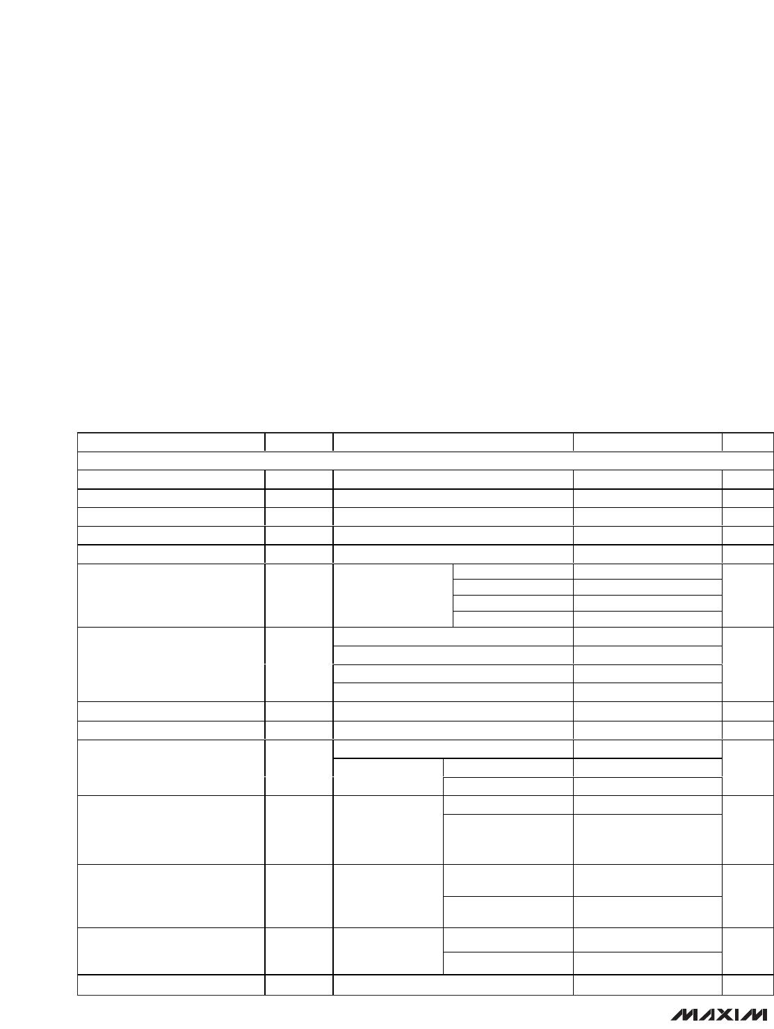
♦ Filterless Amplifier Passes FCC-Radiated
Emissions Standards with 24in of Cable
♦ Unique Spread-Spectrum Mode and Active
Emissions Limiting (AEL) Achieves Better than
20dB Margin Under FCC Limits
♦ Zero Dead Time (ZDT) H-Bridge Maintains State-
of-the-Art Efficiency and THD+N
♦ Simple Master-Slave Setup for Stereo Operation
♦ Up to 90% Efficiency
♦ 2.3W into 4Ω (1% THD+N)
♦ Low 0.02% THD+N (P
OUT
= 1W, V
DD
= 5.0V)
♦ High PSRR (75dB at 217Hz)
♦ Integrated Click-and-Pop Suppression
♦ Low Quiescent Current (5.4mA)
♦ Low-Power Shutdown Mode (0.3µA)
♦ Short-Circuit and Thermal-Overload Protection
♦ Available in Thermally Efficient, Space-Saving
Packages
10-Pin TDFN (3mm x 3mm x 0.8mm)
12-Bump UCSP (1.5mm x 2mm x 0.6mm)
♦ Pin-for-Pin Compatible with the MAX9700 and
MAX9712
MAX9705
2.3W, Ultra-Low-EMI, Filterless,
Class D Audio Amplifier
________________________________________________________________
Maxim Integrated Products
1
Ordering Information
19-3405; Rev 3; 5/09
EVALUATION KIT
AVAILABLE
Cellular Phones
PDAs
MP3 Players
Portable Audio