6N1135, 6N1136
www.vishay.com
Vishay Semiconductors
End of Life January-2018 - Alternative Device: 6N135, 6N136
Rev. 1.9, 13-Nov-12
4
Document Number: 83909
For technical questions, contact: optocoupleranswers@vishay.com
THIS DOCUMENT IS SUBJECT TO CHANGE WITHOUT NOTICE. THE PRODUCTS DESCRIBED HEREIN AND THIS DOCUMENT
ARE SUBJECT TO SPECIFIC DISCLAIMERS, SET FORTH AT www.vishay.com/doc?91000
Note
As per IEC 60747-5-5, §7.4.3.8.1, this optocoupler is suitable for “safe electrical insulation” only within the safety ratings. Compliance with
the safety ratings shall be ensured by means of protective circuits.
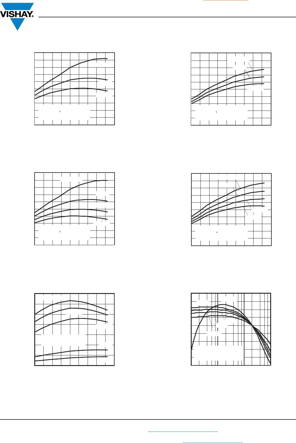
TYPICAL CHARACTERISTICS (T
amb
= 25 °C, unless otherwise specified)
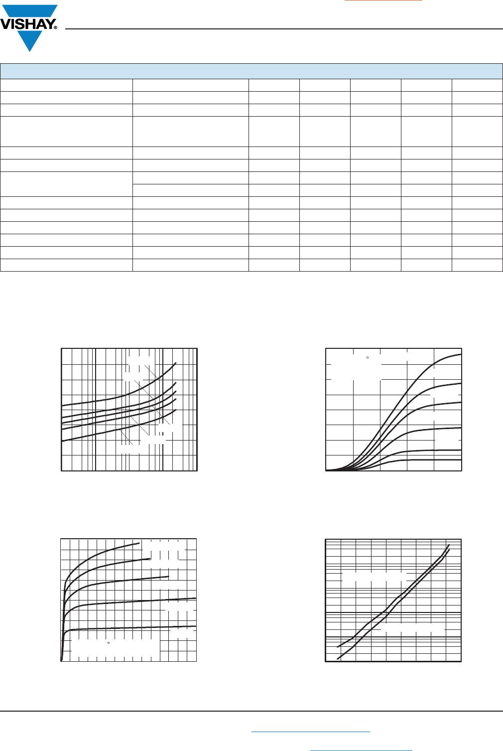
Fig. 3 - Forward Voltage vs. Forward Current
Fig. 4 - Collector Current vs. Collector Emitter Voltage
Fig. 5 - Collector Current vs. Collector Emitter Voltage
Fig. 6 - Collector Emitter Dark Current vs. Ambient Temperature
SAFETY AND INSULATION RATINGS
PARAMETER TEST CONDITION SYMBOL MIN. TYP. MAX. UNIT
Climatic classification According to IEC 68 part 1 - 55 / 110 / 21 -
Pollution degree (DIN VDE 0109) - 2 -
Comparative tracking index per
DIN IEC112/VDE 0303 part 1,
group IIIa per DIN VDE 6110
CTI 175 - 399
V
IOTM
V
IOTM
8000 - - V
V
IORM
V
IORM
630 - - V
Isolation resistance
V
IO
= 500 V, T
amb
= 25 °C R
IO
10
12
--Ω
V
IO
= 500 V, T
amb
= 100 °C R
IO
10
11
--Ω
P
SI
P
SI
- - 500 mA
I
SI
I
SI
- - 300 mW
T
SI
T
SI
- - 175 °C
Creepage distance 8 - - mm
Clearance distance 7 - - mm
Insulation thickness 0.4 - - mm
0.7
0.9
1.1
1.3
1.5
1.7
1.9
2.1
2.3
0.01 0.10 1.00 10.00 100.00
I
F
- Forward Current (mA )17585
V - Forward Voltage (V)
F
110 °C
50 °C
25 °C
- 55 °C
0
1
2
3
4
5
6
7
8
9
10
11
12
0 1 2 3 4 5 6 7 8 9 10 1112131415
V
CE
- Collector Emitter Voltage (V)17586
I - Collector Current (mA )
T
amb
= 25 C,
V
CC
= 5 V, non-saturated
C
I
F
= 25 mA
20 mA
15 mA
10 mA
5 mA
0
1
2
3
4
5
6
7
8
0.0 0.1 0.2 0.3 0.4 0.5
V
CE
- Collector Emitter Voltage (V)17629
I - Collector Current (mA)
T
amb
= 25 C,
V
CC
= 5 V,
saturated
C
I
F
= 25 mA
20 mA
15 mA
10 mA
5 mA
1 mA
- 55 - 35 - 15 5 25 45 65 85 105 125
I - Collector Emitter Leakage Current (nA)
T
amb
- Ambient Temperature (°C)17590
CE0
100
10
0.1
0.01
1000
V
CC
= V
CE
= 15 V
1
V
CC
= V
CE
= 5 V
6N1135, 6N1136
www.vishay.com
Vishay Semiconductors
End of Life January-2018 - Alternative Device: 6N135, 6N136
Rev. 1.9, 13-Nov-12
5
Document Number: 83909
For technical questions, contact: optocoupleranswers@vishay.com
THIS DOCUMENT IS SUBJECT TO CHANGE WITHOUT NOTICE. THE PRODUCTS DESCRIBED HEREIN AND THIS DOCUMENT
ARE SUBJECT TO SPECIFIC DISCLAIMERS, SET FORTH AT www.vishay.com/doc?91000
Fig. 7 - Normalized Current Transfer Ratio vs.
Ambient Temperature
Fig. 8 - Normalized Current Transfer Ratio vs.
Ambient Temperature
Fig. 9 - Output Current vs. Temperature
Fig. 10 - Normalized Current Transfer Ratio vs.
Ambient Temperature
Fig. 11 - Normalized Current Transfer Ratio vs.
Ambient Temperature
Fig. 12 - Normalized h
FE
vs. Base Current
0.00
0.25
0.50
0.75
1.00
1.25
1.50
1.75
2.00
2.25
2.50
- 55 - 35 - 15 5 25 45 65 85 105 125
T
amb
- Ambient Temperature (°C)17631
CTR - Normalized CTR
Normalized to I
F
= 16 mA,
T
amb
= 25 C, V
CC
= 5 V
V
O
= 0.4 V, saturated
Norm
10 mA
5 mA
I
F
= 1 mA
16 mA
0
1
2
3
4
5
6
7
- 55 - 35 - 15 5 25 45 65 85 105 125
T
amb
- Ambient Temperature (°C)17587
I - Collector Current (mA)
V
CC
= 5 V,
V
O
= 0.4 V, saturated
C
I
F
= 20 mA
16 mA
10 mA
2 mA
1 mA
0.0
0.2
0.4
0.6
0.8
1.0
1.2
1.4
1.6
1.8
2.0
- 55 - 35 - 15 5 25 45 65 85 105 125
T
amb
- Ambient Temperature (°C)17632
CTR - Normalized CTR
Normalized to I
F
= 10 mA,
T
amb
= 25 C, V
CC
= 5 V
V
O
= 5 V, non saturated
Norm
10 mA
5 mA
I
F
= 1 mA
0.0
0.2
0.4
0.6
0.8
1.0
1.2
1.4
1.6
1.8
2.0
- 55 - 35 - 15 5 25 45 65 85 105 125
T
amb
- Ambient Temperature (°C)17633
CTR - Normalized CTR
Normalized to I
F
= 16 mA,
T
amb
= 25 C, V
CC
= 5 V
V
O
= 5 V, non saturated
Norm
10 mA
5 mA
I
F
= 1 mA
16 mA
0.5
0.6
0.7
0.8
0.9
1.0
1.1
1.2
1.3
1.4
0.10 1.00 10.00 100.00
I
B
- Base Current (mA)
17634
Normalized h
FE
Normalized to
I
B
= 20 μA, T
amb
= 25 °C
V
O
= 5 V, non saturated
110 ºC
0 ºC
50 ºC
25 ºC
- 55 ºC
6N1135, 6N1136
www.vishay.com
Vishay Semiconductors
End of Life January-2018 - Alternative Device: 6N135, 6N136
Rev. 1.9, 13-Nov-12
6
Document Number: 83909
For technical questions, contact: optocoupleranswers@vishay.com
THIS DOCUMENT IS SUBJECT TO CHANGE WITHOUT NOTICE. THE PRODUCTS DESCRIBED HEREIN AND THIS DOCUMENT
ARE SUBJECT TO SPECIFIC DISCLAIMERS, SET FORTH AT www.vishay.com/doc?91000
Fig. 13 - Normalized h
FE
vs. Base Current
Fig. 14 - Photo Current vs. Forward Current
Fig. 15 - Photo Current vs. Forward Current
Fig. 16 - Switching Time vs. Load Resistance
Fig. 17 - Switching Time vs. Load Resistance
Fig. 18 - Propagation Delay vs. Ambient Temperature
0.0
0.2
0.4
0.6
0.8
1.0
1.2
1.4
1.6
1.8
2.0
0.10 1.00 10.00 100.00
I
B
- Base Current (mA) 17635
Normalized h
FE
Normalized to
I
B
= 20 μA, T
amb
= 25 °C
V
O
= 0.4 V, saturated
110 °C
0 °C
50 °C
25 °C
- 55 °C
0.01
0.1
1
10
100
0.01 0.1 1 10 100
I
F
- Forward Current (mA)
17636
I
p
- Photo Current (μA)
110 °C
50 °C
25 °C
0 °C
- 55 °C
V
CC
= 5 V
0.01 0.10 1.00 10.00 100.00
I
F
- Forward Current (mA)17637
Norm. Photo Current
110 °C
50 °C
25 °C
0 °C
- 55 °C
V
CC
= 5 V
normalized to
I
F
= 16 mA
0.0001
0.001
0.01
0.1
1
10
0
500
1000
1500
2000
2500
3000
0.0 0.5 1.0 1.5 2.0 2.5
R
L
- Load Resistance (k )Ω
17638
t - Switching Time (ns)
V
CC
= V
O
= 5 V,
I
F
= 16 mA
T
amb
= 25 °C
t
off
t
on
0
5000
10 000
15 000
20 000
25 000
0 5 10 15 20
R
L
- Load Resistance (kΩ) 17639
t - Switching Time (ns)
V
CC
= V
O
= 5 V,
I
F
= 16 mA
T
amb
= 25 °C
t
off
t
on
0
200
400
600
800
1000
1200
1400
1600
1800
- 55 - 35 - 15 5 25 45 65 85 105 125
T
amb
- Ambient Temperature (°C)
17588
t - Propagation Delay time (ns)
V
CC
= 5 V, I
F
= 16 mA
R
L
= 1.9 kΩ, T
amb
= 25 °C
P
t
PLH
(3 V)
t
PHL
(3 V)
t
PHL
(1.5 V)
t
PLH
(1.5 V)

6N1136-X006

Mfr. #:
Manufacturer:
Vishay Semiconductors
Description:
High Speed Optocouplers 1Mbd High-Speed Trans Out CTR>15%
Lifecycle:
New from this manufacturer.
Delivery:
DHL FedEx Ups TNT EMS
Payment:
T/T Paypal Visa MoneyGram Western Union