ADuM3300/ADuM3301 Data Sheet
Rev. D | Page 14 of 20
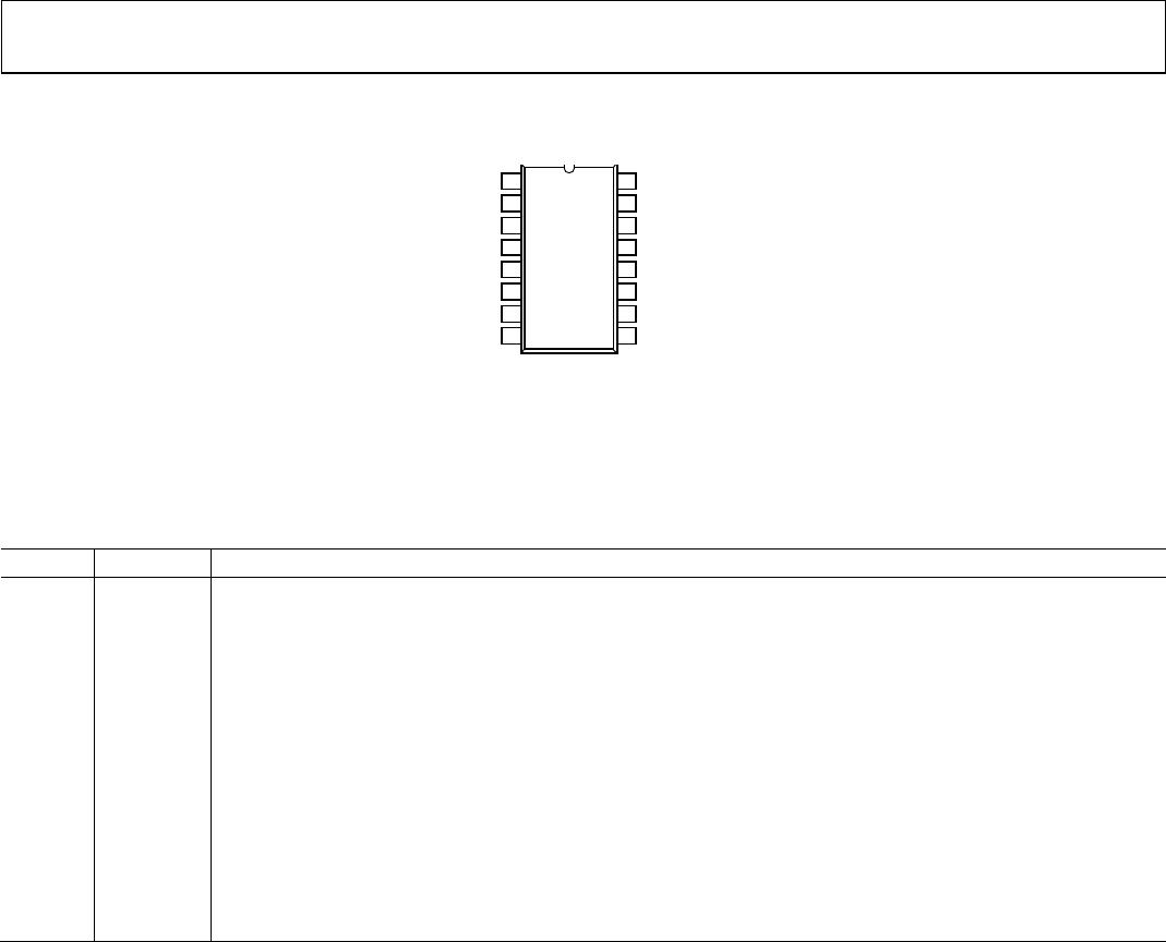
V
DD1
1
*GND
1
2
V
IA
3
V
IB
4
V
DD2
16
GND
2
**
15
V
OA
14
V
OB
13
V
OC
5
V
IC
12
NC
6
NC
11
V
E1
7
V
E2
10
*GND
1
8
GND
2
**
9
NC = NO CONNECT
ADuM3301
TOP VIEW
(Not to Scale)
05984-005
*PIN 2 AND PIN 8 ARE INTERNALLY CONNECTED,
AND CONNECTING BOTH TO GND
1
IS RECOMMENDED.
*PIN 9 AND PIN 15 ARE INTERNALLY CONNECTED,
AND CONNECTING BOTH TO GND
2
IS RECOMMENDED.
Figure 5. ADuM3301 Pin Configuration
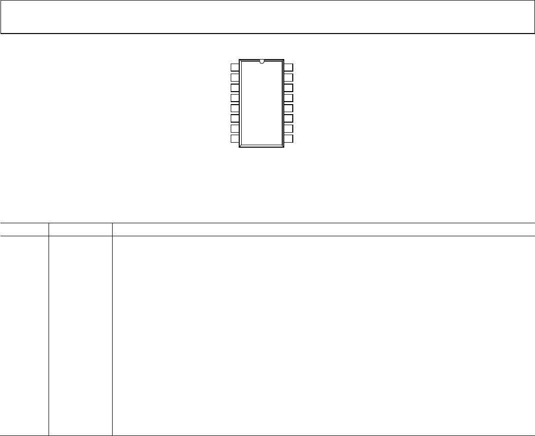
Table 13. ADuM3301 Pin Function Descriptions
Pin No. Mnemonic Description
1 V
DD1
Supply Voltage for Isolator Side 1, 3.0 V to 5.5 V.
2, 8 GND
1
Ground 1. Ground reference for Isolator Side 1.
3 V
IA
Logic Input A.
4 V
IB
Logic Input B.
5 V
OC
Logic Output C.
6, 11 NC
No Connect.
7 V
E1
Output Enable 1. Active high logic input. V
OC
output is enabled when V
E1
is high or disconnected. V
OC
is
disabled when V
E1
is low. In noisy environments, connecting V
E1
to an external logic high or low is
recommended.
9, 15 GND
2
Ground 2. Ground reference for Isolator Side 2.
10 V
E2
Output Enable 2. Active high logic input. V
OA
and V
OB
outputs are enabled when V
E2
is high or disconnected.
V
OA
and V
OB
outputs are disabled when V
E2
is low. In noisy environments, connecting V
E2
to an external logic
high or low is recommended.
12 V
IC
Logic Input C.
13 V
OB
Logic Output B.
14 V
OA
Logic Output A.
16 V
DD2
Supply Voltage for Isolator Side 1, 3.0 V to 5.5 V.