ATTENUATORS - DIGITAL - SMT
1
HMC539ALP3 /539ALP3E
v01.0416
0.25 dB LSB GaAs MMIC 5-BIT DIGITAL
POSITIVE CONTROL ATTENUATOR, DC - 4 GHz
For price, delivery, and to place orders: Analog Devices, Inc.,
One Technology Way, P.O. Box 9106, Norwood, MA 02062-9106
Phone: 781-329-4700 • Order online at www.analog.com
Application Support: Phone: 1-800-ANALOG-D
Information furnished by Analog Devices is believed to be accurate and reliable. However, no
responsibility is assumed by Analog Devices for its use, nor for any infringements of patents or other
rights of third parties that may result from its use. Specications subject to change without notice. No
license is granted by implication or otherwise under any patent or patent rights of Analog Devices.
Trademarks and registered trademarks are the property of their respective owners.
Functional Diagram
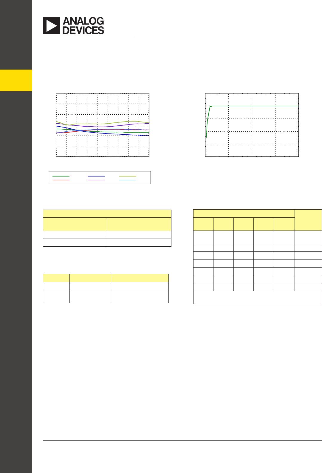
Electrical Specications,
T
A
= +25° C, With Vdd = +5V & Vctl = 0/+5V (Unless Otherwise Noted)
The HMC539ALP3/539ALP3E is ideal for both RF
and IF applications:
• Cellular Infrastructure
• ISM, MMDS, WLAN, WiMAX, WiBro
• Microwave Radio & VSAT
• Test Equipment and Sensors
0.25 dB LSB Steps to 7.75 dB
± 0.05 dB Typical Step Error
Low Insertion Loss: 0.7 dB
High IP3: +62 dBm
Single Control Line Per Bit
TTL/CMOS Compatible Control
Single +3V to +5V Supply
3x3 mm SMT Package
The HMC539ALP3/539ALP3E is a broadband
5-bit GaAs IC digital attenuator in a low cost lead-
less surface mount package. This single positive
control line per bit digital attenuator utilizes an off
chip AC ground capacitor for near DC operation,
making it suitable for a wide variety of RF and IF
applications. Covering DC to 4 GHz, the inser-
tion loss is less than 0.7 dB typical. The attenuator
bit values are 0.25 (LSB), 0.5, 1, 2, and 4 dB for a
total attenuation of 7.75 dB. Attenuation accuracy is
excellent at ± 0.05 dB typical step error. The attenu-
ator also features a high IIP3 of +62 dBm. Five TTL/
CMOS control inputs are used to select each attenua-
tion state. A single Vdd bias of +3V to +5V is required.
Parameter Frequency (GHz) Min. Typ. Max. Units
Insertion Loss
DC - 1.5 GHz
1.5 - 3.0 GHz
3.0 - 4.0 GHz
0.7
1.0
1.3
1.0
1.3
1.7
dB
dB
dB
Attenuation Range DC - 4 GHz 7.75 dB
Return Loss (RF1 & RF2, All Atten. States)
DC - 3 GHz
3.0 - 4.0 GHz
27
25
dB
dB
Attenuation Accuracy:
(Referenced to Insertion Loss)
All States
DC - 3 GHz
3.0 - 4.0 GHz
± (0.2 + 2% of Atten. Setting) Max.
± (0.2 + 4% of Atten. Setting) Max.
dB
dB
Input Power for 0.1 dB Compression 0.1 - 4.0 GHz 32 dBm
Input Third Order Intercept Point
(Two-Tone Input Power= 15 dBm Each Tone)
0.1 - 4.0 GHz 62 dBm
Switching Characteristics
tRISE, tFALL (10/90% RF)
tON, tOFF (50% CTL to 10/90% RF)
DC - 4 GHz
45
52
ns
ns
Typical Applications Features
General Description