Data Sheet ADM1810 to ADM1813/ADM1815 to ADM1818
Rev. F | Page 7 of 12
THEORY OF OPERATION
TIMING DIAGRAMS FOR ALL DEVICES
The following two timing diagrams are valid for ADM1810,
ADM1811, ADM1812, ADM1813, ADM1815, ADM1816,
ADM1817, and ADM1818.
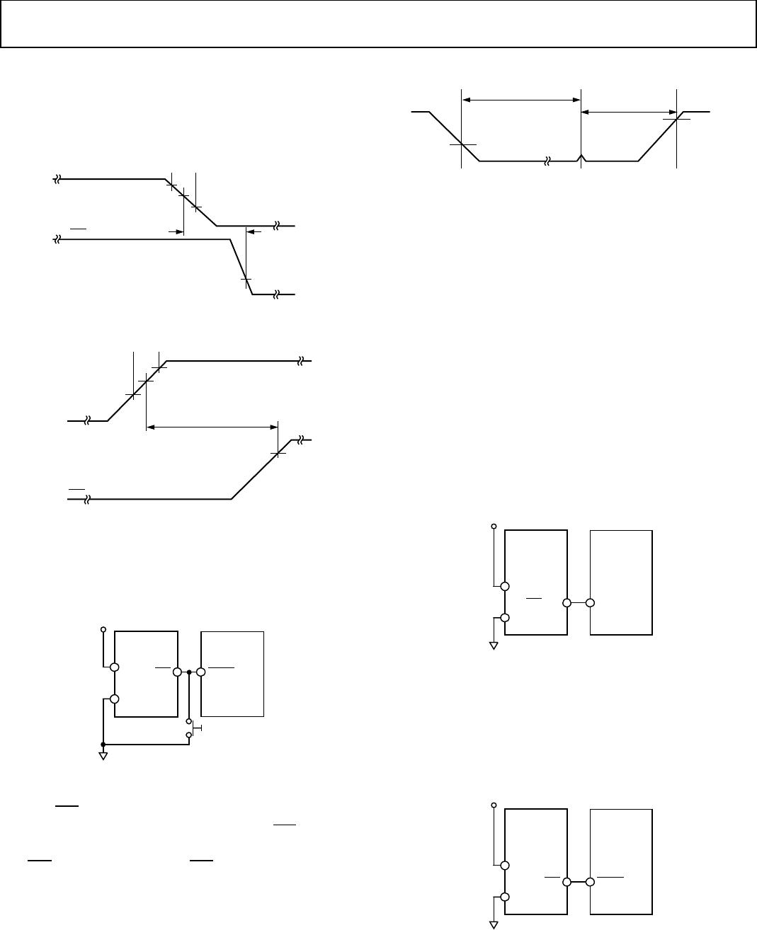
Figure 9. Power-Down Timing Diagram
Figure 10. Power-Up Timing Diagram
ADM1813 AND ADM1818
The ADM1813 and ADM1818 are low cost voltage monitoring
devices featuring an open-drain with internal pull-up resistor
output and optional push-button reset function.
Figure 11. ADM1813/ADM1818 Typical Application
An optional push-button reset switch can be connected
between
RST
and ground. Pressing this switch pulls the reset
output low. If the push-button reset button pulls the
RST
output
low for a period greater than 1 µs when the reset button releases
the
RST
line to float high, then the
RST
line stays low for another
150 ms typical.
Figure 12. Push-Button Reset Timing Diagram
The ADM1818 range has 2.88 V and 2.55 V (typical) trip point
options that allow the user to monitor 3.3 V and 3 V supplies.
For 5 V monitoring requirements, the ADM1813 range has 4.62 V
and 4.35 V (typical) trip point options.
ADM1810, ADM1812, ADM1815, AND ADM1817
The ADM1812 is a 5 V supply monitor with an active high
push-pull output and trip point options of 4.62 V and 4.35 V
typical. The ADM1810 is similar to the ADM1812, except that
the ADM1810 has an active low push-pull output stage. The
ADM1817 is suitable for monitoring 3.3 V, 3 V, and 2.5 V
supplies, with an active high push-pull output and trip point
options of 3.06 V, 2.88 V, 2.55 V, 2.31 V, and 2.18 V typical.
The ADM1815 is similar to the ADM1817, except that the
ADM1815 has an active low push-pull output stage.
The ADM1810/ADM1812/ADM1815/ADM1817 can connect
directly to most microprocessor reset inputs without the need
for external components.
Figure 13. ADM1810/ADM1812/ADM1815/ADM1817 Typical Application
ADM1811 AND ADM1816
The ADM1811 is a 5 V supply monitor with an active low open-
drain with internal pull-up resistor output and trip point options of
4.62 V and 4.35 V typical. The ADM1816 also has an active low
open-drain with internal pull-up resistor output but is suitable
for monitoring lower voltage supplies of 3.3 V, 3 V, a n d 2 . 5 V.
Figure 14. ADM1811/ADM1816 Typical Application
00064-008
V
CC
V
CC
TRIP POINT (MAX)
V
CC
TRIP POINT (MIN)
V
OL
V
CC
TRIP POINT
V
CC
TO RESET
DELAY
RST
00064-009
V
CC
V
CC
TRIP POINT (MAX)
RESET ACTIVE TIMEOUT
V
CC
TRIP POINT (MIN)
V
CC
TRIP POINT
RST
00064-010
ADM1813/
ADM1818
V
CC
GND
RST
V
CC
MICRO-
PROCESSOR
RESET
00064-011
VOLTAGE
INPUT HIGH
PUSH-BUTTON TIME
RESET TIMEOUT
VOLTAGE
INPUT LOW
00064-012
ADM1810/
ADM1812/
ADM1815/
ADM1817
V
CC
GND
RST/RST
V
CC
MICRO-
PROCESSOR
RESET
00064-013
ADM1811/
ADM1816
V
CC
GND
RST
V
CC
MICRO-
PROCESSOR
RESET