Data Sheet DAC08
Rev. D | Page 3 of 21
SPECIFICATIONS
ELECTRICAL CHARACTERISTICS
V
S
= ±15 V, I
REF
= 2.0 mA, 55°C ≤ T
A
≤ +125°C for DAC08/DAC08A, 0°C ≤ T
A
≤ +70°C for DAC08E and DAC08H, −40°C to +85°C for
DAC08C, unless otherwise noted. Output characteristics refer to both I
OUT
and
I
OUT.
Table 1.
Parameter Symbol Test Conditions/Comments
DAC08A/DAC08H DAC08E DAC08C
Unit Min Typ Max Min Typ Max Min Typ Max
RESOLUTION
8
8
8
Bits
MONOTONICITY
8
8
8
Bits
NONLINEARITY NL
±0.1
±0.19
±0.39
%FS
SETTLING TIME t
S
To ±1/2 LSB, all bits switched
on or off, T
A
= 25°C
1
85 135
85 150
85 150 ns
PROPAGATION DELAY
Each Bit
t
PLH
A
1
35
60
35
60
35
60
ns
All Bits Switched t
PHL
35 60
35 60
35 60 ns
FULL-SCALE TEMPCO
1
TCI
FS
±10 ±50
±10 ±80
±10 ±80 ppm/°C
DAC08E
±50
OUTPUT VOLTAGE
Compliance V
OC
Full-scale current
(True Compliance)
Change <1/2 LSB, R
OUT
>
20 MΩ typ
10
+18 10
+18 10
+18 V
FULL RANGE CURRENT
I
FR4
REF
5.000 kΩ T
A
= 25°C
1.984
1.992
2.000
1.94
1.99
2.04
1.94
1.99
2.04
mA
FULL RANGE
SYMMETRY
I
FRS
I
FR4
− I
FR2
±0.5 ±4
±1 ±8
±2 ±16 µA
ZERO-SCALE CURRENT I
ZS
0.1 1
0.2 2
0.2 4 µA
OUTPUT CURRENT
RANGE
I
OR1
R14, R15 = 5.000 k 2.1
2.1
2.1
mA
I
OR2
V
REF
= +15.0 V, V= 10 V
V
REF
= +25.0 V, 4.2
4.2
4.2
mA
V− = 12 V
OUTPUT CURRENT
NOISE
I
REF
= 2 mA
25
25
25
nA
LOGIC INPUT LEVELS
Logic 0
V
IL
LC
0.8
0.8
0.8
V
Logic 1 V
IL
2
2
2
V
LOGIC INPUT CURRENT
V
LC
= 0 V
Logic 0 I
IL
V
IN
= 10 V to +0.8 V
−2 10
−2 10
−2 10 µA
Logic 1 I
IH
V
IN
= 2.0 V to 18 V
0.002 10
0.002 10
0.002 10 µA
LOGIC INPUT SWING V
IS
V− = 15 V 10
+18 10
+18 10
+18 V
LOGIC THRESHOLD
RANGE
V
THR
V
S
= ±15 V
1
10
+13.5 10
+13.5 10
+13.5
V
REFERENCE BIAS
CURRENT
I
15
−1 −3
−1 −3
−1 −3 µA
REFERENCE INPUT dI/dt R
EQ
= 200 4 8
4 8
4 8
mA/µs
SLEW RATE
R
L
= 100
C
C
= 0 pF. See Figure 7.
1
DAC08 Data Sheet
Rev. D | Page 4 of 21
Parameter Symbol Test Conditions/Comments
DAC08A/DAC08H DAC08E DAC08C
Unit Min Typ Max Min Typ Max Min Typ Max
POWER SUPPLY
SENSITIVITY
PSSI
FS+
V+ = 4.5 V to 18 V
±0.0003 ±0.01
±0.0003 ±0.01
±0.0003 ±0.01
%∆I
O
/
%∆V+
PSSI
FS
V− = 4.5 V to 18 V
±0.002 ±0.01
±0.002 ±0.01
±0.002 ±0.01
%∆I
O
/
%∆V−
I
REF
= 1.0 mA
POWER SUPPLY
CURRENT
I+
S
REF
2.3
3.8
2.3
3.8
2.3
3.8
mA
I−
4.3 5.8
4.3 5.8
4.3 5.8 mA
I+ V
S
= +5 V, 15 V
2.4 3.8
2.4 3.8
2.4 3.8 mA
I− I
REF
= 2.0 mA
6.4 7.8
6.4 7.8
6.4 7.8 mA
I+ V
S
= ±15 V
2.5 3.8
2.5 3.8
2.5 3.8 mA
I−
REF
6.5
7.8
6.5
7.8
6.5
7.8
mA
POWER DISSIPATION P
D
±5 V, I
REF
= 1.0 mA +5 V,
15 V
33 48
33 48
33 48 mW
I
REF
= 2.0 mA ±15 V, I
REF
=
2.0 mA
108 136
103 136
108 136 mW
135 174
135 174
135 174 mW
1
Guaranteed by design.
TYPICAL ELECTRICAL CHARACTERISTICS
V
S
= ±15 V, and I
REF
= 2.0 mA, unless otherwise noted. Output characteristics apply to both I
OUT
and
I
OUT.
Table 2.
Parameter Symbol Test Conditions/Comments All Grades Typical Unit
REFERENCE INPUT SLEW RATE dI/dt 8 mA/µs
PROPAGATION DELAY t
PLH
, t
PHL
T
A
= 25°C, any bit 35 ns
SETTLING TIME t
S
To ±1/2 LSB, all bits switched on or
off, T
A
= 25°C
85 ns
Data Sheet DAC08
Rev. D | Page 5 of 21
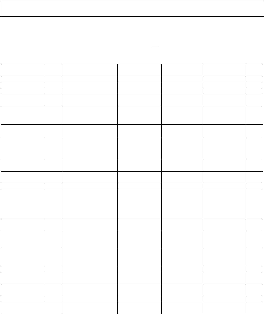
ABSOLUTE MAXIMUM RATINGS
Table 3.
Parameter Rating
Operating Temperature
DAC08AQ, DAC08Q −55°C to +125°C
DAC08HQ, DAC08EQ, DAC08CQ 0°C to +70°C
DAC08CP, DAC08CS −40°C to +85°C
Junction Temperature (T
J
) −65°C to +150°C
Storage Temperature Q Package −65°C to +150°C
Storage Temperature P Package −65°C to +125°C
Lead Temperature (Soldering, 60 sec) 300°C
V+ Supply to V− Supply 36 V
Logic Inputs V− to V− + 36 V
V
LC
V− to V+
Analog Current Outputs (at V
S−
= 15 V) 4.25 mA
Reference Input (V
14
to V
15
) V− to V+
Reference Input Differential Voltage
(V
14
to V
15
) ±18 V
Reference Input Current (I
14
) 5.0 mA
Stresses at or above those listed under Absolute Maximum
Ratings may cause permanent damage to the product. This is a
stress rating only; functional operation of the product at these
or any other conditions above those indicated in the operational
section of this specification is not implied. Operation beyond
the maximum operating conditions for extended periods may
affect product reliability.
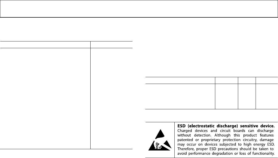
THERMAL RESISTANCE
θ
JA
is specified for worst case mounting conditions, that is, θ
JA
is
specified for device in socket for CERDIP, PDIP, and LCC
packages; θ
JA
is specified for device soldered to printed circuit
board for SOIC package.
Table 4. Thermal Resistance
Package Type θ
JA
θ
JC
Unit
16-Lead CERDIP (Q) 100 16 °C/W
16-Lead PDIP (P) 82 39 °C/W
20-Terminal LCC (RC) 76 36 °C/W
16-Lead SOIC (S) 111 35 °C/W
ESD CAUTION

DAC08CSZ-REEL

Mfr. #:
Manufacturer:
Analog Devices Inc.
Description:
Digital to Analog Converters - DAC IC 8-BIT HIGH-Spd MULTIPLY
Lifecycle:
New from this manufacturer.
Delivery:
DHL FedEx Ups TNT EMS
Payment:
T/T Paypal Visa MoneyGram Western Union