C3D25170H

1
Subject to change without notice.
www.cree.com/power
D
a
t
as
h
e
e
t
:
C
3
D
2
5
1
7
0
H
R
e
v
.
-
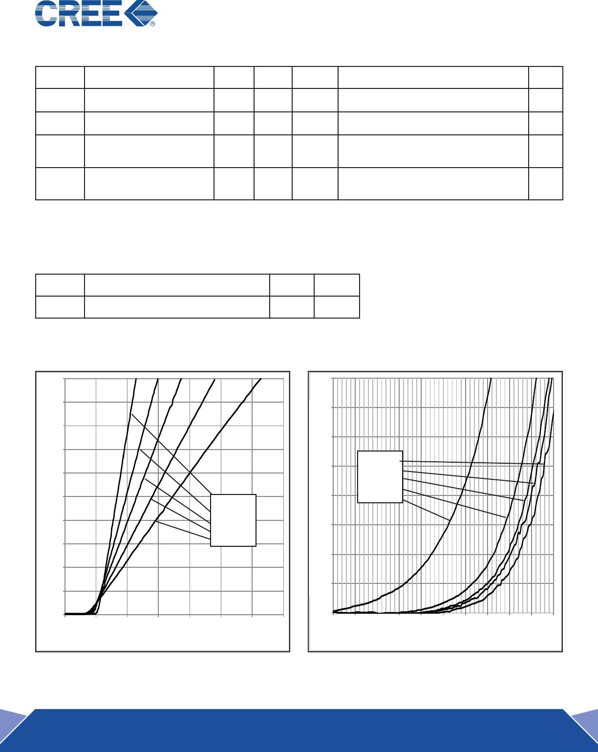
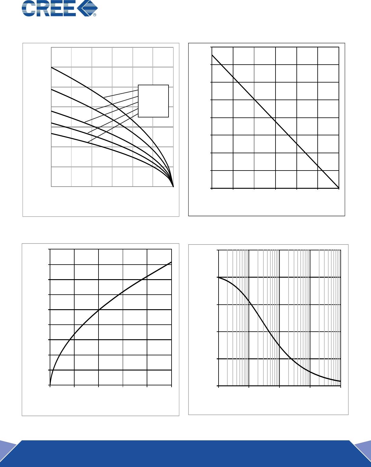
C3D25170H–Silicon Carbide Schottky Diode
Z-Rec
RectifieR
Features
1700-Volt Schottky Rectier
Zero Reverse Recovery Current
Zero Forward Recovery Voltage
High-Frequency Operation
Temperature-Independent Switching Behavior
Extremely Fast Switching
Halogen-Free; RoHS Complaint
Benets
Replace Bipolar with Unipolar Rectiers
Essentially No Switching Losses
Higher Efciency
Reduction of Heat Sink Requirements
Parallel Devices Without Thermal Runaway
Package
Maximum Ratings
Symbol Parameter Value Unit Test Conditions Note
V
RRM
Repetitive Peak Reverse Voltage 1700 V
V
RSM
Surge Peak Reverse Voltage 1700 V
V
DC
DC Blocking Voltage 1700 V
I
F
Continuous Forward Current 26.3 A T
C
<135˚C
I
FRM
Repetitive Peak Forward Surge Current
99
57
A
T
C
=25˚C, t
P
=10 ms, Half Sine Wave, D=1
T
C
=110˚C, t
P
=10 ms, Half Sine Wave, D=1
I
FSM
Non-Repetitive Peak Forward Surge
Current
117
88
A
T
C
=25˚C, t
P
=10ms, Half Sine Wave, D=1
T
C
=110˚C, t
P
=10 ms, Half Sine Wave, D=1
P
tot
Power Dissipation
377
163
W
T
C
=25˚C
T
C
=110˚C
T
c
Maximum Case Temperature 135 ˚C
T
J
Operating Junction Range
-55 to
+175
˚C
T
stg
Storage Temperature Range
-55 to
+135
˚C
TO-247 Mounting Torque
1
8.8
Nm
lbf-in
M3 Screw
6-32 Screw
Part Number Package Marking
C3D25170H TO-247-2 C3D25170
V
RRM
= 1700 V
I
F;
T
C
<135˚C = 26.3 A
Q
c
= 230 nC
PIN 1
PIN 2
CASE
2 C3D25170H Rev. -
0
5
10
15
20
25
30
35
40
45
50
0 1 2 3 4 5 6 7
Electrical Characteristics
Symbol Parameter Typ. Max. Unit Test Conditions Note
V
F
Forward Voltage
1.8
3.2
2.5
4
V
I
F
= 25 A T
J
=25°C
I
F
= 25 A T
J
=175°C
I
R
Reverse Current
20
100
100
400
μA
V
R
= 1700 V T
J
=25°C
V
R
= 1700 V T
J
=175°C
Q
C
Total Capacitive Charge 230 nC
V
R
= 1700 V, I
F
= 25 A
di/dt = 200 A/μs
T
J
= 25°C
C Total Capacitance
2079
187.5
97
pF
V
R
= 0 V, T
J
= 25°C, f = 1 MHz
V
R
= 200 V, T
J
= 25˚C, f = 1 MHz
V
R
= 800 V, T
J
= 25˚C, f = 1 MHz
Note:
1. This is a majority carrier diode, so there is no reverse recovery charge.
Thermal Characteristics
Symbol Parameter Typ. Unit
R
θJC
Thermal Resistance from Junction to Case 0.4 °C/W
Typical Performance
Figure 1. Forward Characteristics
0
1
2
3
4
5
6
7
8
0 200 400 600 800 1000 1200 1400 1600 1800 2000
Figure 2. Reverse Characteristics
I
F
(A)
V
F
(V)
I
R
(μA)
V
R
(V)
T
J
=-55°C
T
J
= 25°C
T
J
= 75°C
T
J
=125°C
T
J
=175°C
T
J
=-55°C
T
J
= 25°C
T
J
= 75°C
T
J
=125°C
T
J
=175°C
3 C3D25170H Rev. -
Typical Performance
0
20
40
60
80
100
120
140
25
50
75
100
125
150
175
I
F(peak)
(A)
T
C
˚C
T
C
˚C
P
Tot
(W)
Figure 3. Current Derating
0
500
1000
1500
2000
2500
0.1 1 10 100 1000
Figure 4. Power Derating
0
20
40
60
80
100
120
140
160
180
0 200 400 600 800 1000
Figure 5. Recovery Charge vs. Reverse Voltage Figure 6. Capacitance vs. Reverse Voltage
Qrr (nC)
V
R
(V)
C (pF)
V
R
(V)
10% Duty
30% Duty
50% Duty
70% Duty
DC

C3D25170H

Mfr. #:
Manufacturer:
N/A
Description:
Schottky Diodes & Rectifiers SIC SCHOTTKY DIODE 1700V, 25A
Lifecycle:
New from this manufacturer.
Delivery:
DHL FedEx Ups TNT EMS
Payment:
T/T Paypal Visa MoneyGram Western Union

Products related to this Datasheet