DCMC 472 U 400 DC 2 B S
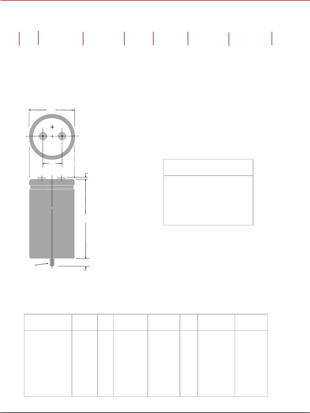
Diam. (D) Length (L) Terminals (S) Typical Weight
Case Code ±.031 Inches ±.78 mm ±.062 Inches ±1.57 mm ±0.015 Inches ±.38 mm
oz g
AK 1.375 34.93 1.625 41.28 0.50 12.70 1.9 54
AA 1.375 34.93 2.125 53.98 0.50 12.70 2.0 57
AH 1.375 34.93 2.625 66.68 0.50 12.70 2.7 77
AB 1.375 34.93 3.125 79.38 0.50 12.70 3.3 94
AJ 1.375 34.93 3.625 92.08 0.50 12.70 3.8 108
AC 1.375 34.93 4.125 104.78 0.50 12.70 4.4 125
AD 1.375 34.93 4.625 117.48 0.50 12.70 5.1 145
AE 1.375 34.93 5.125 130.18 0.50 12.70 6.8 193
AF 1.375 34.93 5.625 142.88 0.50 12.70 8.1 230
EA 1.750 44.45 2.125 53.98 0.75 19.05 2.7 76
EH 1.750 44.45 2.625 66.68 0.75 19.05 3.8 108
EB 1.750 44.45 3.125 79.38 0.75 19.05 5.1 145
EJ 1.750 44.45 3.625 92.08 0.75 19.05 6.8 193
EC 1.750 44.45 4.125 104.78 0.75 19.05 8.1 230
ED 1.750 44.45 4.625 117.48 0.75 19.05 9.0 255
EE 1.750 44.45 5.125 130.18 0.75 19.05 9.5 269
EF 1.750 44.45 5.625 142.88 0.75 19.05 10.5 298
BA 2.000 50.80 2.125 53.98 0.88 22.23 5.4 153
BH 2.000 50.80 2.625 66.68 0.88 22.23 6.1 173
BB 2.000 50.80 3.125 79.38 0.88 22.23 6.8 193
BJ 2.000 50.80 3.625 92.08 0.88 22.23 8.2 232
BC 2.000 50.80 4.125 104.78 0.88 22.23 9.5 269
BD 2.000 50.80 4.625 117.48 0.88 22.23 10.3 292
BE 2.000 50.80 5.125 130.18 0.88 22.23 10.7 303
BF 2.000 50.80 5.625 142.88 0.88 22.23 13.0 369
CH 2.500 63.50 2.625 66.68 1.13 28.58 9.2 261
CB 2.500 63.50 3.125 79.38 1.13 28.58 10.4 295
CJ 2.500 63.50 3.625 92.08 1.13 28.58 12.7 361
CC 2.500 63.50 4.125 104.78 1.13 28.58 15.0 425
CD 2.500 63.50 4.625 117.48 1.13 28.58 17.2 488
CE 2.500 63.50 5.125 130.18 1.13 28.58 19.3 547
CF 2.500 63.50 5.625 142.88 1.13 28.58 21.4 607
DB 3.000 76.20 3.125 79.38 1.25 31.75 16.7 473
DJ 3.000 76.20 3.625 92.08 1.25 31.75 20.0 567
DC 3.000 76.20 4.125 104.78 1.25 31.75 22.2 629
DD 3.000 76.20 4.625 117.48 1.25 31.75 25.5 723
DE 3.000 76.20 5.125 130.18 1.25 31.75 30.0 850
DF 3.000 76.20 5.625 142.88 1.25 31.75 31.9 904
DM 3.000 76.20 6.625 168.28 1.25 31.75 34.4 933.5
DP 3.000 76.20 5.875 149.23 1.25 31.75 32.8 931
DN 3.000 76.20 7.625 193.68 1.25 31.75 39.5 1119
DG 3.000 76.20 8.625 219.08 1.25 31.75 43.3 1227
FC 3.500 88.90 4.125 104.78 1.25 31.75 30.0 850
FD 3.500 88.90 4.625 117.48 1.25 31.75 34.4 976
FE 3.500 88.90 5.125 130.18 1.25 31.75 40.5 1148
FF 3.500 88.90 5.625 142.88 1.25 31.75 43.1 1221
FP 3.500 88.90 5.875 149.23 1.25 31.75 44.3 1257
FN 3.500 88.90 7.625 193.68 1.25 31.75 53.3 1512
FG 3.500 88.90 8.625 219.08 1.25 31.75 58.5 1658
FM 3.500 88.90 6.625 168.28 1.25 31.75 46.4 1315.4
Uninsulated Case Dimensions For insulated case, add 0.024”(0.610 mm) to “D”and 0.030”(0.762 mm) to height.
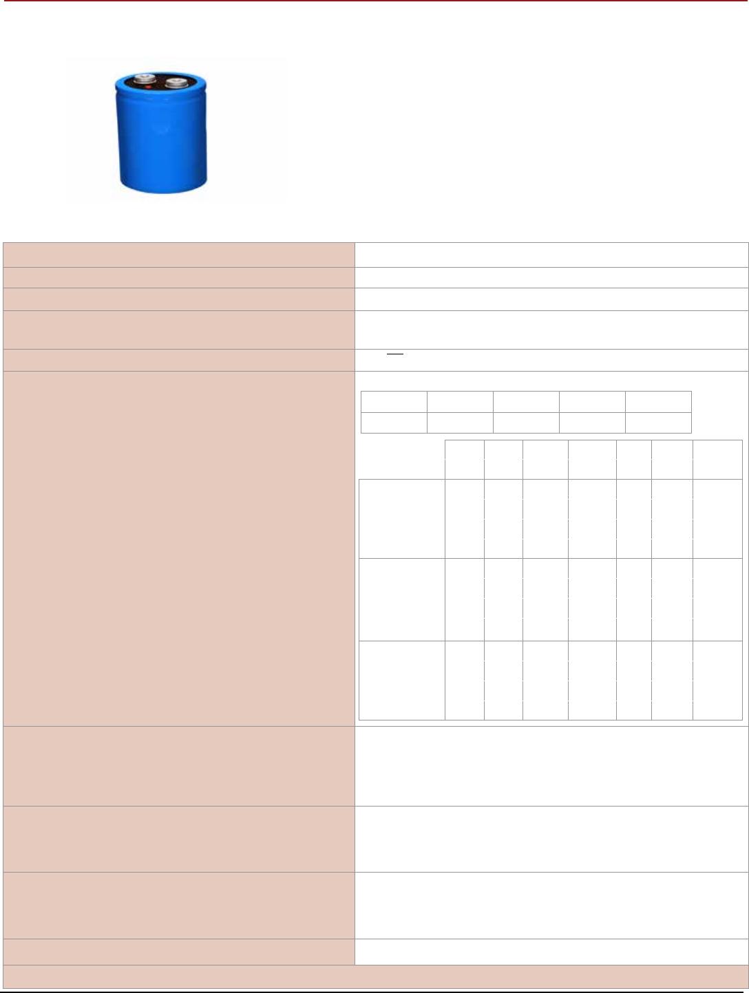
Type DCMC 85 °C High Capacitance, Screw Terminal, Aluminum
Highest Capacitance Screw Terminal Type
CDM Cornell Dubilier • 140 Technology Place • Liberty, SC 29657 • Phone: (864)843-2277 • Fax: (864)843-3800